How to Choose a Fiber Patch Panel

A fiber patch panel looks like a simple box of ports, but the one that fits your network is not the one with the most ports. Order the wrong panel and you find out at the worst moment: on site, with a terminated cable that no longer reaches the adapter row, or a splice tray that was never included. Re-terminating costs hours of technician time, so the selection process is worth doing once, in the right order.
This guide walks through a five-step decision chain that starts from the cable plant you already have, not from a catalog: fiber type and count, connector and polish, termination method, mounting and density, and cost drivers. Work through it top to bottom and the panel you specify will terminate cleanly, survive the move-add-change cycle, and leave room for the next speed upgrade. A short checklist at the end turns the whole process into a one-page spec sheet you can send to any supplier.
Start With the Cable Plant, Not the Catalog
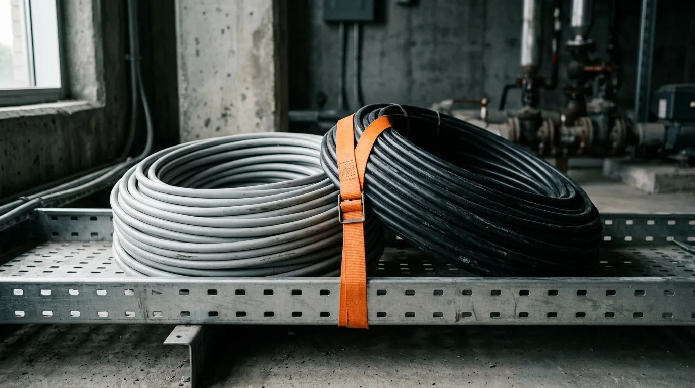
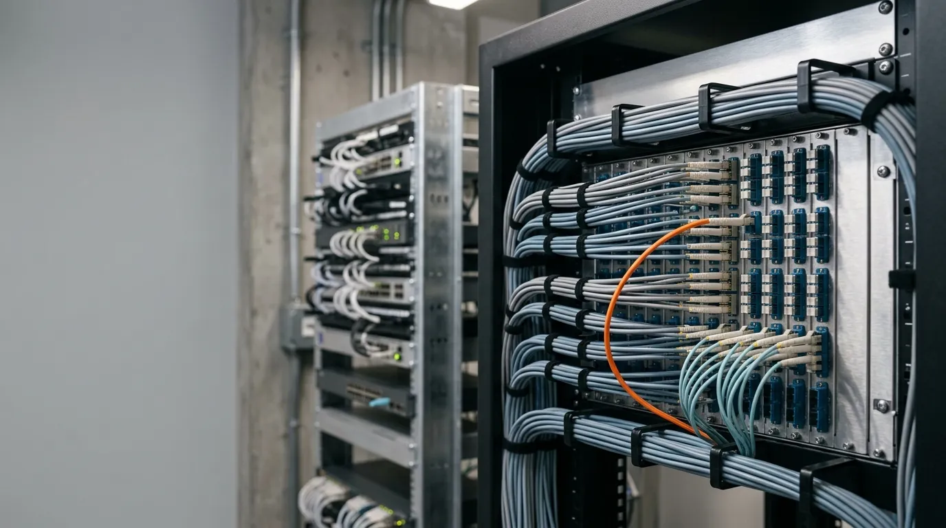
A fiber optic patch panel is a passive enclosure that terminates incoming fiber strands at a row of adapters, so they can be patched to switches, servers, or other panels with short fiber patch cords. It gives the network a central, labeled, protected point where connections can be changed without touching the trunk cable. If you already know what a patch panel does, the useful question is which one your project needs — and that is decided by the cable plant, not by the rack.
Every panel selection starts with five inputs, and each one narrows the choice among the main fiber patch panel types:
- Fiber type and count — single-mode or multimode, and how many strands enter the panel.
- Connector and polish — LC, SC, or MPO on the patch-cord side, plus UPC or APC end faces.
- Termination method — fusion-spliced pigtails (with splice trays) or directly terminated connectors.
- Mounting and density — rack-mount 1U/2U/4U, wall-mount, or high-density cassette panels.
- Cost drivers — which specs actually move the price, so you budget before you quote.
Work these in order. Each step produces the input the next one needs: the fiber count sets the port count, the port count plus connector sets the rack height, and so on. This is the same logic that governs the wider enterprise structured cabling design — panels are specified as part of the cabling system, not as standalone boxes.
Step 1: Match the Fiber Type and Fiber Count
The first question is not "how many ports" but "what cable is coming into the panel." Two properties of that cable decide everything downstream: its mode and its strand count.
Mode. Single-mode fiber (OS1/OS2) carries one light path and is built for long reach — campus backbones, building risers, and anything that may one day run 10G+ over hundreds of meters or kilometers. Multimode fiber (OM1–OM5) carries multiple light paths over short distances — typically 70–150 m for 40G/100G links — and dominates inside data centers and floors. The mode sets the adapter color coding and the connector polish you will use. If you are still deciding between the two, our single-mode vs multimode comparison covers the trade-offs; for this guide, assume the cable already exists.
Strand count. Bulk fiber cables bundle strands in groups of 12, so common counts are 12, 24, 48, 96, and 144. Most jackets print the count and mode, usually in a form like "12F SM" or "24F OM4" — if only a part number is printed, look it up before ordering anything. The strand count entering the panel determines the minimum port capacity, but there is a counting trap here that causes most ordering mistakes.
Ports vs. fibers: the counting trap. A "port" on a fiber patch panel is one adapter opening. For duplex connector families like LC and SC, one connection uses two fibers (transmit and receive), and most panels list capacity in LC duplex ports. So:
What you have | What it means | Panel you need |
|---|---|---|
12-fiber trunk cable | 6 duplex connections | 12-port LC panel (12 fibers) or 6-port duplex-counted |
24-fiber trunk cable | 12 duplex connections | 24-port LC panel (24 fibers) |
"48-fiber panel" in a vendor catalog | 48 fibers = 24 LC duplex ports | 24-port LC panel |
48-port LC panel | 48 LC duplex ports = 96 fibers | for 96-fiber trunks or high-density zones |
When a catalog says "24-port," always confirm whether it means 24 fibers or 24 duplex ports — the two differ by a factor of two. The same ambiguity follows you into MPO panels, where a "12-fiber" MPO port carries 12 or 24 fibers in one ferrule depending on the version. Asking this one question in the RFQ eliminates the most common ordering error in fiber panels.
Step 2: Choose the Connector and Polish (LC, SC, MPO, and APC vs UPC)
The panel's adapters must match the connectors on your patch cords and equipment. Four families cover almost every enterprise and data center installation:
- LC — the default for high-density patching; a small 1.25 mm ferrule, available simplex or duplex. Most 1U panels use LC because it doubles the port count per rack unit compared with SC.
- SC — a larger 2.5 mm push-pull connector, common on single-mode trunk links and older enterprise gear. Easy to handle, slightly lower density.
- ST — a bayonet-style connector still found in legacy multimode and industrial installations.
- FC — a threaded single-mode connector common on lab test equipment and telecom transmission gear.
- MPO/MTP — a multi-fiber rectangular ferrule carrying 8, 12, or 24 fibers in one connector, used for parallel optics (40G/100G/400G) and high-density trunking. The fiber connector types article covers the full family if you need a refresher.
Match the panel's adapter type to the connector that will be plugged in most often — in practice, patch cords, not the trunk, set the adapter. A data center running LC transceivers wants LC panels even if the incoming trunk is spliced from a 12-fiber cable; the pigtail side uses LC, the trunk side splices in the tray.
UPC vs APC. The second half of connector selection is the end-face polish, and it matters more than most buyers realize. UPC (ultra-polished, blue) is the default for most single-mode patching; multimode links typically use PC (physical contact) polish, and APC (angled, green) is required on single-mode PON, RFoG, and any link where return loss matters. You cannot mix the two on one link — an APC connector will not mate safely with a UPC adapter — so the panel's adapter color must match your planned patch cords. For the full comparison of loss and reflection behavior, see our APC vs UPC guide.
Color coding (TIA-598). Adapter colors follow the fiber mode: beige for OM1, black for OM2, aqua for OM3/OM4, lime for OM5, blue for single-mode UPC, green for single-mode APC. The TIA-598-C color code reference published by the FOA is the standard chart technicians use on site. Order panels whose adapter colors match the cable plant, and label the panel face accordingly — it saves every future technician from having to trace the fiber before touching a connection.
Step 3: Decide How the Panel Gets Terminated (Splice vs Direct)
This step decides whether the panel needs splice trays, which changes both the internal layout and the cost. There are two ways to terminate a trunk cable into a panel:
Fusion splicing to pigtails. The trunk strands are fusion-spliced to short, factory-terminated pigtails, and the pigtail connectors plug into the panel's internal adapters. The splice points are protected and organized in splice trays — hinged cassettes inside the panel that hold splice protectors and route slack. This is the standard field method: it is fast, consistent, and produces the lowest loss at the splice. It also requires the panel to physically accommodate the trays, so if your contractor will splice (the common case for 12+ fiber trunks), confirm the panel includes or accepts splice trays before ordering.

Splice trays keep fusion-spliced pigtail joints protected and organized inside the panel.
Direct termination. Connectors are installed directly onto the trunk strands with field-termination kits. No splice trays are needed, but field termination is slower and more skill-dependent, and it is usually reserved for small fiber counts or pre-terminated cable assemblies ordered from the factory. Panels for direct termination can be shallower and cheaper — but only if you are sure the installation will not splice later.
A related choice is loaded vs. unloaded. A loaded panel ships with adapters (and often pigtails) installed; an unloaded panel is an empty chassis with blank plates. Unloaded panels look less convenient, but they are the right choice when the connector type or fiber count may change before the panel is populated — you buy only the adapter panels (faceplates) you need today and expand later. Loaded panels win when the spec is fixed and the installer wants to plug and patch immediately.
Whichever method you choose, the panel needs enough internal room for slack storage and bend radius: factory spec sheets list a minimum bend radius (typically 10× the cable diameter for patch cords), and panel designers assume the slack loops inside the panel respect it. A panel that is too shallow for the incoming fiber count will force sharp bends at the entry grommets — the kind of micro-bend that shows up later as an intermittent loss that is very hard to trace.
Step 4: Pick the Mounting and Density (Rack, Wall, and High-Density MPO)
Now the mechanical decision: where does the panel live, and how much fiber must fit there?
Rack height. Rack-mount fiber patch panels occupy 1U, 2U, or 4U of a standard 19-inch rack, where one rack unit is 1.75 inches (44.45 mm) as defined by the EIA-310 rack standard. Typical capacities, for LC duplex panels:
Panel | Typical LC capacity | Best for |
|---|---|---|
1U fixed | 24–48 fibers (12–24 duplex ports) | general patching, manageable density |
1U high-density | 96+ fibers with sliding trays | dense zones where rack space is tight |
2U | 48–96 fibers, more tray space | trunks that need splicing plus patching |
4U | 96–192 fibers | distribution frames and large trunks |
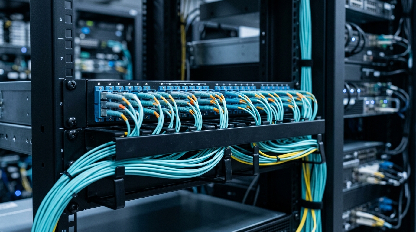
A rack-mount fiber patch panel with front cable management keeps patching clean and traceable.
The density band is a trade-off: a 1U high-density panel saves rack space but makes the fiber harder to access, so sliding or drawer-style panels exist to pull the termination area forward. If technicians will patch the panel weekly, favor accessible 1U/2U designs over cramming 288 fibers into a single U.
Wall-mount. When there is no rack — a telecom closet, a retail site, a small server room — wall-mount fiber patch panels (usually 12 to 48 fibers) terminate and protect the same way in a compact enclosure. Outdoor fiber patch panels and industrial variants add NEMA-rated housings, DIN-rail mounting, or sealed glands for dust and moisture; specify those only when the environment demands them.
High-density MPO. In data centers, the density step usually means MPO. An MPO fiber patch panel takes 12-fiber (or 24-fiber) MPO trunk connectors on the back through cassettes and breaks them out to LC duplex ports on the front — 2, 4, or more cassettes per 1U.

MPO cassette panels break 12-fiber trunks out to LC duplex ports at high density.
This is where polarity becomes a spec item, not a footnote. MPO links must manage fiber position across the whole channel, and the three standard methods (A, B, and C) flip fibers differently between ends; a panel's cassettes and trunk patch cords must use the same method or the link will not light up. Our MPO-12 vs MPO-16 vs MPO-24 article compares the fiber-count options, and the FS MPO polarity guide explains methods A/B/C with diagrams — worth reading before you specify cassettes, because swapping methods after installation means replacing patch cords.
If you are designing the distribution points for a campus or multi-building network rather than a single rack, the campus fiber network design guide shows how panels fit into the overall architecture — same selection logic, applied at building scale.
Step 5: Budget for the Real Cost Drivers (Not Just the Price Tag)
"How much does a patch panel cost?" is one of the most-asked questions about fiber panels, and the honest answer is that it depends on five or six spec decisions — not on a single list price. Understanding the drivers lets you budget, and keeps the RFQ honest when the low bid arrives.
Cost driver | Impact on price | What to watch |
|---|---|---|
Port count / density | High | A 48-port panel costs roughly double a 24-port; high-density 1U versions cost more per port than relaxed 2U layouts |
Loaded vs. unloaded | Medium | Loaded adds adapters + often pigtails; unloaded chassis is cheaper but add adapter plates later |
Chassis build | Medium | Steel chassis, powder coating, sliding trays, hinged doors — ruggedness scales with the environment |
Connector type | Medium | MPO and cassette systems cost more than plain LC fixed panels; APC adapters slightly more than UPC |
Brand / certification | Low–medium | Certified, documented panels (test reports, standards compliance) carry a premium that pays off in audits |
Accessories | Medium | Splice trays, pigtails, cable managers, labels — often 20–40% on top of the chassis price |
The budget logic follows from the earlier steps: fixed LC duplex patching on a floor is the low-cost case; spliced trunks, high-density cassettes, and APC single-mode are the premium cases. Two practical rules: (1) if you expect one density upgrade in the panel's life, buy the unloaded chassis and load it as needed — you pay the chassis once instead of replacing it; (2) if the installation will be spliced, make sure the quoted price includes splice trays and pigtails, because "panel only" quotes conveniently leave them out. For a sense of current configurations and options, TTI Fiber's fiber optic patch panel range shows what loaded, unloaded, sliding, and wall-mount panels look like in practice — useful as a checklist of options before you send the RFQ.
The Standards That Should Govern Your Spec
Selection guides often skip standards, but the standards are what make your panel choice defensible — to your own team, to the auditor, and to the next engineer who inherits the network. Four matter most:
Standard | What it governs | How to use it in selection |
|---|---|---|
Structured cabling: component performance, transmission requirements, cabling topology | Match panel and adapter specs to the cabling category your links must support | |
Data center infrastructure: tiers, redundancy, cabling architecture | Confirm the panel layout supports the access/patching model your tier assumes | |
TIA-606 | Administration and labeling of cabling infrastructure | Order panels with writable label strips; plan the labeling scheme before install |
IEC 61754 | Connector interface standards (LC, SC, MPO, etc.) | Use it to verify connector/adapter intermateability across vendors |
TIA-568.3 is the fiber-specific part of the structured cabling standard — it defines performance requirements for the components (cables, connectors, panels) and the transmission specs they must meet. TIA-942 adds the data center layer: cabling zones, access types, and the redundancy expectations per tier. Neither standard tells you "1U or 2U," but both give you the vocabulary to demand verified performance from a supplier instead of accepting "it will be fine." For a broader introduction to fiber technology and its standards, the FOA's fiber reference is the industry's open textbook.
One more reason standards matter: when you ask a vendor "does this panel meet TIA-568.3 and TIA-942 expectations?" the quality of the answer tells you a lot about the product. A supplier that produces test data is signaling a different grade of manufacturing than one that answers with a catalog page.
Final Checklist Before You Order
Print this, fill it in, and attach it to the RFQ. Ten lines, ten minutes, and it eliminates the ordering errors that cause site callbacks:
- Fiber mode — single-mode (OS2) or multimode (OM3/OM4/OM5)? Adapter colors must match.
- Strand count — how many fibers enter the panel? (Groups of 12: 12 / 24 / 48 / 96…)
- Port count — confirm "24-port" means 24 fibers or 24 duplex ports. (Ask. Twice.)
- Connector — LC, SC, ST, or MPO on the patching side? Matches your patch cords and transceivers?
- Polish — UPC or APC? All-green or all-blue, never mixed.
- Termination — splice to pigtails (needs splice trays) or direct termination? Are trays included?
- Loaded or unloaded — fixed spec → loaded; likely changes → unloaded chassis + adapter plates.
- Mounting — rack 1U/2U/4U, or wall-mount? High-density sliding trays if weekly patching?
- MPO polarity — if cassettes: same polarity method (A/B/C) across cassettes and trunk cords?
- Accessories and verification — splice trays, pigtails, cable managers, labels, test reports included?
Two habits that pay off: verify the panel's actual installed depth against your cable slack allowance before ordering, and ask for insertion-loss test data on a sample unit. The second habit is worth more than any spec sheet — a panel that arrives with measured per-port loss is a panel whose manufacturing process is under control.
FAQ
What is the point of a patch panel? A fiber patch panel is the termination and patching point that protects the trunk cable, centralizes connection changes, and lets technicians test or reroute links without touching the permanent cabling. It is where the patch panel concept meets fiber: the same manageability copper panels give you, applied to optical links.
How do you connect fiber optic cable to a patch panel? Strip and clean the cable, then either fusion-splice the strands to pigtails (and store the splices in the tray) or terminate connectors directly onto the strands. The connectors plug into the panel's adapters on the front; patch cords then link the panel ports to equipment. Test each link with a power meter or OTDR after termination — a panel that tests clean before the doors close is a panel you will not revisit.
Do fiber patch panels reduce speed? No — a correctly terminated, clean panel is transparent to the signal. Losses come from dirty connectors, mismatched polishes, or tight bends, not from the panel itself. This is why insertion-loss testing matters at install time.
What is the difference between a fiber patch panel and a fiber distribution panel? In most catalogs the two terms describe the same device — a termination enclosure with adapter rows. When a vendor does distinguish them, "distribution panel" usually means a larger frame (floor-standing or 4U+ ODF) that also handles splicing and slack for many fibers, while "patch panel" refers to the rack-mount unit. If the distinction matters for your quote, ask the vendor which form factor their "distribution" product actually is.
The five steps take longer to read than to run: count the fibers, pick the connector and polish, choose the termination method, fix the mounting and density, and let the cost drivers set the budget. Fill out the checklist, and the panel that arrives on site is the panel that terminates cleanly — no rework, no emergency splicing, no second order. When you are ready to compare real configurations, TTI Fiber's rack-mount and wall-mount patch panel range (linked above) is a practical place to start.