Campus Fiber Network Design: A Beginner's Guide
Why Fiber for Your Campus Backbone?
A university IT director recently told us: "We ran new Cat6A between buildings three years ago. Now we need 10 Gigabit to the engineering lab, and the copper won't reach." That conversation repeats itself across corporate campuses, hospital networks, and industrial parks every day.
Copper Ethernet cables hit a hard limit at 100 meters. Wireless point-to-point links struggle with interference and weather. If your buildings sit more than a football field apart — and most campus environments do — fiber optic cable is not an upgrade path. It is the only path.
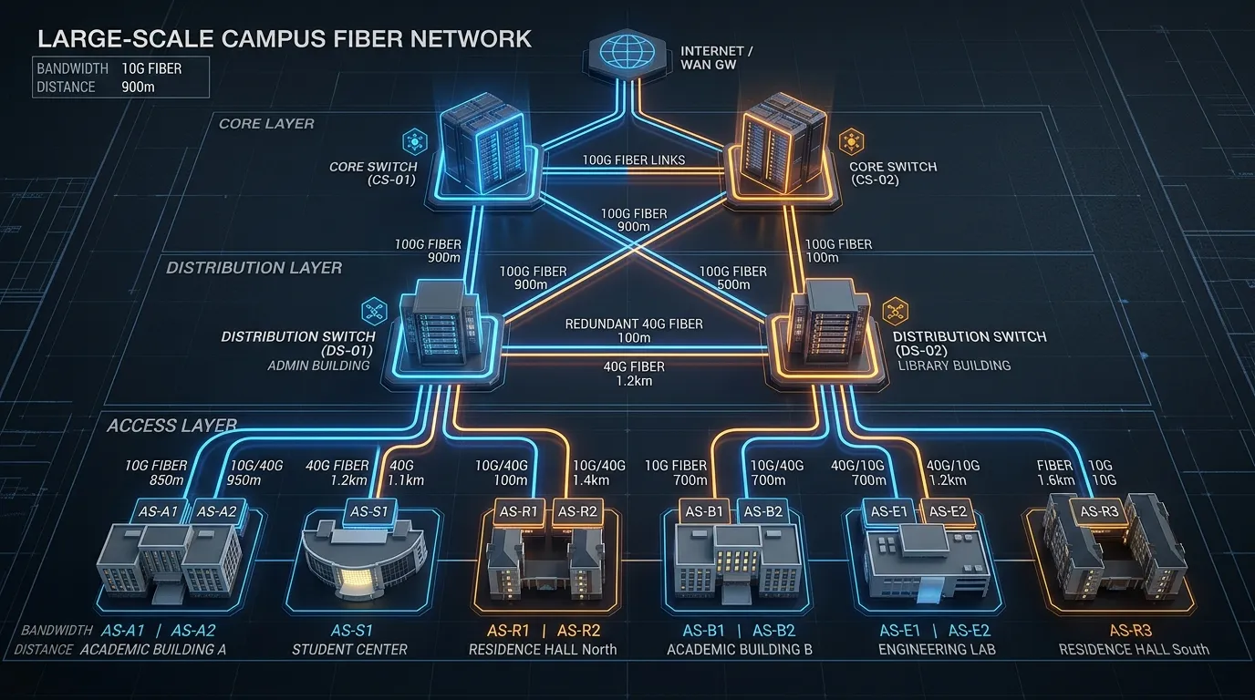
A fiber backbone between campus buildings delivers three things copper and wireless cannot match:
- Distance without signal degradation. Single-mode fiber carries 10 Gbps over 10 kilometers without a repeater — roughly the distance from one end of a large university campus to the other and back.
- Bandwidth headroom for decades. A single fiber pair supports 100 Gbps today with the right optics, and the same glass installed in 2026 will carry 400 Gbps or more with tomorrow's transceivers.
- Electrical isolation. Fiber does not conduct electricity, eliminating ground loops between buildings and surviving lightning strikes that would destroy copper connections.
The question is not whether to use fiber for your campus backbone. The question is how to design it correctly the first time — because trenching between buildings is expensive, and redoing it is rarely in the budget.
The Three-Layer Campus Network Model
Campus network design follows a hierarchical model standardized in TIA-568 structured cabling guidelines and detailed in our structured cabling overview. Understanding these three layers is the foundation every design decision builds on.
Core Layer
The core layer is the high-speed backbone connecting major campus zones — the data center, the main telecommunications room, and the primary distribution nodes. In a campus context, the core typically runs at 40 Gbps or 100 Gbps over single-mode fiber. Think of it as the interstate highway of your network: it carries aggregated traffic from every building at the highest possible speed.
Distribution Layer
The distribution (or aggregation) layer sits between the core and individual buildings. Each building or building cluster gets a distribution switch that connects back to the core via fiber uplinks — usually at 10 Gbps or 25 Gbps. This is where most campus fiber design decisions happen: what fiber type, how many strands, and which pathway between the building and the core.
Access Layer
The access layer is where end users connect — the switches in wiring closets on each floor, feeding individual offices, labs, and wireless access points. While the access layer itself typically uses copper (Cat6A) for the final 100 meters, the connection from the access switch back to the distribution layer is increasingly fiber, especially in new construction.
Every campus fiber project is fundamentally about designing the core-to-distribution and distribution-to-access links. Get those right, and the rest follows.
Single-Mode vs. Multimode — Making the Right Choice
The single most common question in campus fiber design is which fiber type to install. The answer depends on distance and speed requirements — and getting it wrong means either overpaying or limiting your future options.
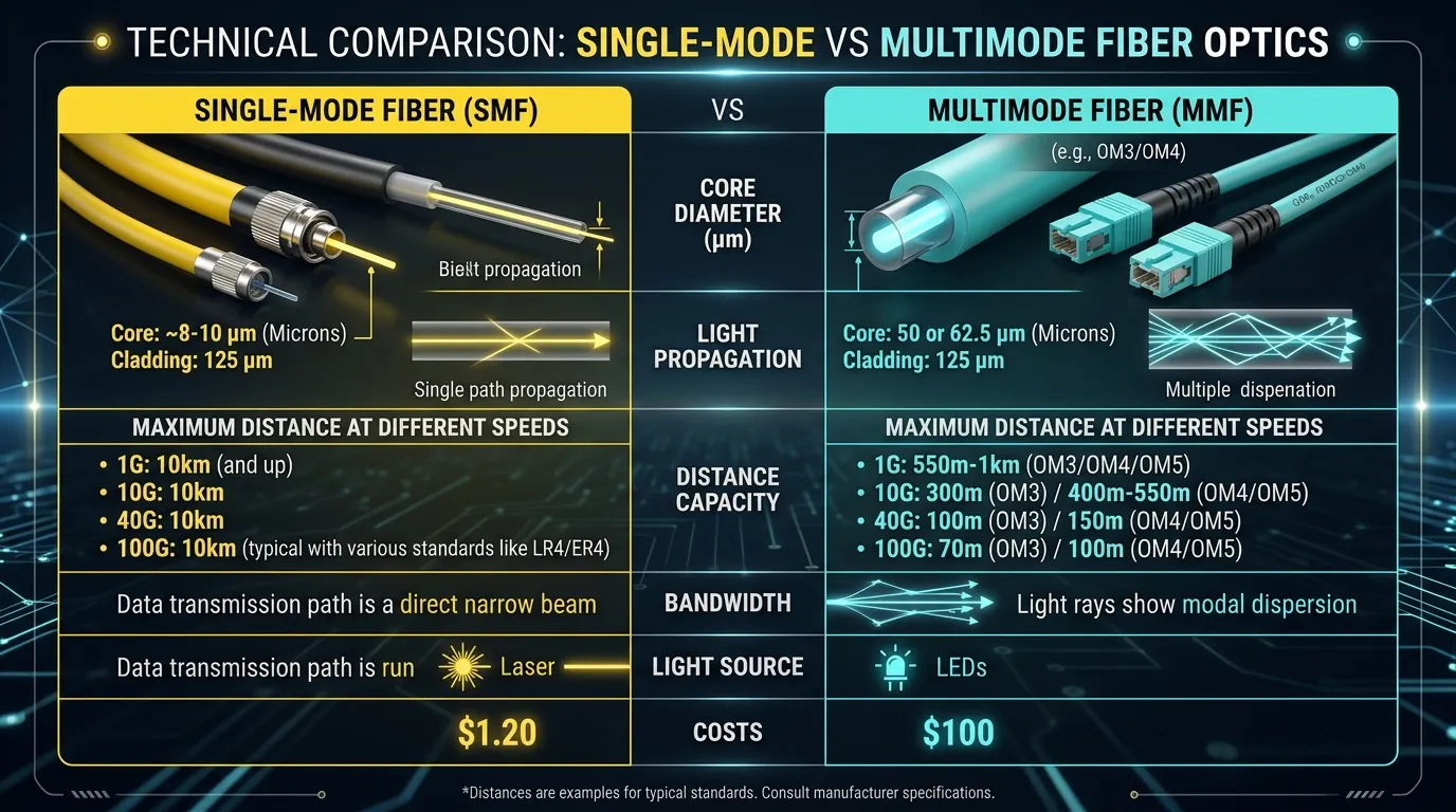
Factor | Single-Mode (OS2) | Multimode (OM4) | Multimode (OM5) |
|---|---|---|---|
Max distance at 10 Gbps | 10+ km | 400 m | 400 m |
Max distance at 40/100 Gbps | 10+ km | 150 m | 150 m (but supports SWDM) |
Cable cost | Lower per meter | Similar | Slightly higher |
Transceiver cost | Higher (FP/DFB lasers) | Lower (VCSEL-based) | Lower (VCSEL-based) |
Future upgrade path | 400G and beyond ready | Limited beyond 100G | Extended via SWDM4 |
Best for | Building-to-building links >300m | Short intra-building backbones | Short links needing wavelength multiplexing |
The Decision Framework
Choose single-mode (OS2) when:
- Any link between buildings exceeds 300 meters — and on most campuses, at least one link will.
- You want 25+ years of speed headroom without re-cabling.
- You are building a new campus backbone from scratch — the marginal cost difference versus multimode is minimal.
Choose multimode (OM4/OM5) when:
- All your links are under 150 meters (intra-building or very compact campus).
- Transceiver cost is the dominant budget concern and you have a high port count.
- You are extending an existing multimode installation.
For most campus backbone projects, single-mode OS2 is the safer default. The fiber itself is less expensive per meter, and while single-mode transceivers cost more, you buy them once per switch port — while the cable stays in the ground for decades. We cover the detailed comparison in our single-mode versus multimode fiber guide.
Practical tip: If budget allows, run a hybrid cable containing both single-mode and multimode fibers. The single-mode strands future-proof the link for speed upgrades; the multimode strands give you lower-cost optics for today's connections.
How Many Fiber Strands Do You Need?
This is where most first-time designers either over-spec (wasting budget on dark fiber that sits unused for 20 years) or under-spec (forcing a re-trench when the organization grows). Neither outcome is good. Here is a systematic approach.
The Calculation Formula
For each building-to-building link, calculate:
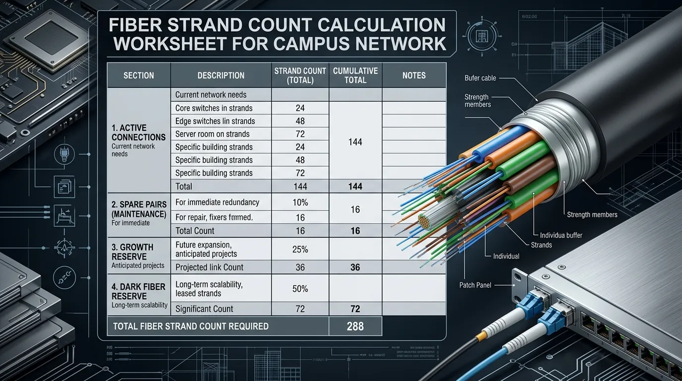
Required strands = (Active connections × 2 strands per duplex link) + (Active connections × 2 spare strands for failover) + (Growth reserve: 50–100% of active total) + (Dark fiber reserve: minimum 12 strands for future uses)
Worked Example
A medium campus with five buildings, each needing two 10 Gbps uplinks to the core:
Component | Strands |
|---|---|
2 active duplex connections × 2 strands | 4 |
2 spare pairs for link aggregation/failover | 4 |
50% growth reserve | 4 |
Dark fiber reserve (security cameras, building management, future tenants) | 12 |
Total per building link | 24 strands |
A 24-strand single-mode cable per building-to-core link typically costs 20–30% more than a 12-strand cable but provides room for expansion without touching the conduit. Most experienced campus designers plan for 24 to 48 strands per backbone link — the labor to pull 48 strands is nearly identical to pulling 12.
When to Use Hybrid Cable
If your campus has a mix of short intra-building links (where multimode transceivers save money) and long inter-building links (where single-mode is mandatory), consider hybrid cables that combine SMF and MMF strands in a single jacket. This gives you flexibility at each endpoint without running separate cables.
Connectors, Patch Panels, and Enclosures — The Physical Layer
The glass is only half the story. The physical hardware that terminates, organizes, and protects your fiber determines whether the network is reliable or a constant source of trouble tickets.
Connector Types
For campus fiber networks, three connector types dominate:
- LC (Lucent Connector): The industry standard for high-density applications. Small form factor, push-pull latching, and used on virtually all modern SFP/SFP+ transceivers. This should be your default choice for patch panels.
- SC (Subscriber Connector): The older standard, still common in legacy installations and some outside plant applications. Square body with push-pull action. If you are extending an existing SC-based plant, stick with SC for consistency.
- MPO/MTP: Multi-fiber connectors that terminate 12 or 24 fibers in a single connector body. Used in high-speed parallel optics (40G/100G SR4) and for high-density backbone trunks. Not needed at every endpoint but worth planning for in main distribution frames.
For a deeper dive into connector options, see our fiber optic connector types guide.
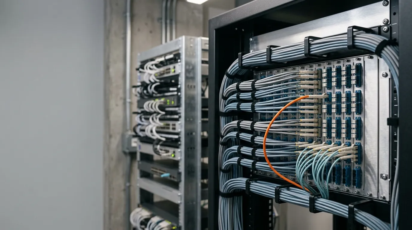
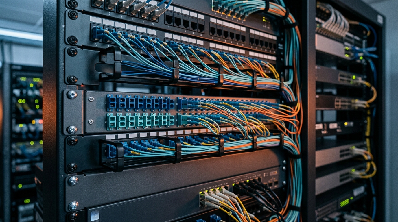
Patch Panels and Enclosures
Each building entry point needs a fiber patch panel or enclosure — this is where the backbone cable terminates and connects to the building's internal network equipment. Key considerations:
- Rack-mount vs. wall-mount: Main telecom rooms use 19-inch rack-mount panels. Smaller buildings or remote closets can use wall-mount enclosures.
- Splice trays: If outside plant cable enters the building, you need splice trays to transition from the heavy outdoor cable to indoor-rated pigtails.
- Labeling: Every port should be labeled with building ID, fiber number, and destination. Future you (or the next person in the role) will thank you.
Planning Your Cable Pathways — Indoor, Outdoor, and Underground
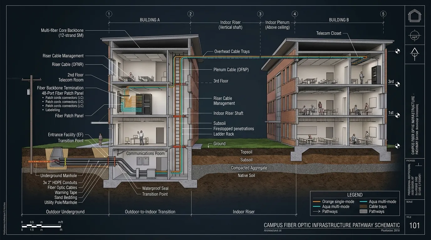
The physical route your fiber takes is as important as the glass inside it. Campus environments mix indoor and outdoor pathways, each with different cable requirements.
Outdoor Pathways
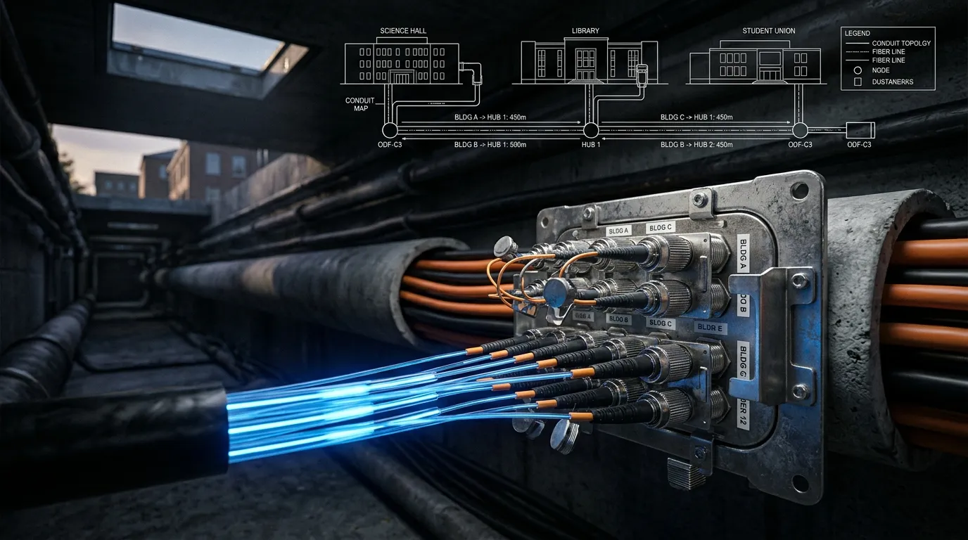
Between buildings, fiber typically runs through underground conduit. Direct-burial cable exists but is rarely the right choice on an active campus — future excavation will find it, and repairs require digging. Use HDPE conduit with pull tape installed, sized at least 50% larger than current needs to accommodate future cable pulls.
Key outdoor specifications:
- Single-mode OS2 cable rated for outdoor use (UV-resistant jacket, water-blocking gel or dry-block technology)
- Armored cable where conduit runs under roadways or parking lots
- Bend-insensitive fiber (G.657) in routes with multiple tight bends — it tolerates smaller bend radii without signal loss
Indoor Pathways
Once fiber enters a building, the cable type changes. Outdoor cable typically must transition to indoor-rated cable within 50 feet of entry (per NEC code). Indoor fiber uses:
- Riser-rated (OFNR) for vertical runs between floors
- Plenum-rated (OFNP) for air-handling spaces above drop ceilings
The transition between outdoor and indoor cable happens at the building entrance facility — typically a wall-mount enclosure with splice trays.
Aerial Options
In some campus environments — particularly industrial parks or rural campuses — aerial fiber strung on existing utility poles can reduce installation costs by 60–70% compared to trenching. The tradeoff is increased vulnerability to storms and vehicle strikes. Aerial deployments require messenger wire support and proper sag/tension calculations.
Testing, Documentation, and Handoff
A fiber network that has not been tested is a fiber network you cannot trust. The FOA fiber optic network design reference emphasizes that testing and documentation are integral to design, not afterthoughts. Plan for testing during the design phase, not after installation.
Essential Tests
- Insertion loss testing with an optical loss test set (OLTS): Measures end-to-end attenuation for every fiber strand. Compare results against your link loss budget — the maximum acceptable loss calculated from connector loss, splice loss, and fiber attenuation over the distance.
- OTDR testing for outside plant segments: An Optical Time Domain Reflectometer trace identifies the exact location of splices, connectors, and any faults along the cable. File these traces as your baseline for future troubleshooting.
- Polarity verification: Ensures that transmit on one end connects to receive on the other — a surprisingly common mistake in multi-fiber installations.
Documentation That Saves Your Future Self
A cable plant record should include:
- A physical topology diagram showing building locations, conduit routes, and cable entry points
- A fiber assignment spreadsheet mapping every strand number to its endpoint and purpose
- OTDR trace files stored with date, technician name, and test parameters
- Photographs of every splice enclosure, patch panel, and building entry point before the ceiling tiles go back in
Standard practice is to deliver one copy to the client and retain one copy for your own records. If a backhoe finds your cable three years from now, the documentation is how you restore service in hours instead of days.
Getting Started: A 5-Step Campus Fiber Design Checklist
- Survey your campus. Map every building, measure distances, and identify existing conduit or pole routes. A walking survey with a laser distance meter is worth more than any amount of desk research.
- Define your bandwidth requirements. Talk to each department about their current usage and 5-year projections. The engineering lab running CFD simulations has different needs than the administration building.
- Select fiber type and count. Start with single-mode OS2 as the default backbone fiber. Calculate strand counts using the formula above. Add at least 50% growth reserve.
- Design the physical plant. Choose connector types (LC for new installations), specify patch panels at each building entry, and plan your cable pathways — underground conduit between buildings, riser-rated indoors.
- Write the test plan before you dig. Define acceptable loss budgets per link, specify which tests will be performed, and designate who signs off on results before the network goes live.
Designing for What Comes Next
A campus fiber network is a 20-to-30-year asset. The trenching, conduit, and pulling labor represent 70–80% of the total installation cost — the fiber cable itself is the inexpensive part. This is why experienced designers run more strands than they think they need and choose fiber types that exceed today's speed requirements.
Single-mode OS2 fiber installed today will carry 400 Gigabit Ethernet, 800 Gigabit, and whatever comes after that. The transceivers at each end will be swapped out over the years, but the glass in the ground stays the same.
If you are starting a campus fiber project and need guidance on component selection — from outdoor-rated single-mode cable to LC patch panels to pre-terminated backbone trunks — the TTI Fiber engineering team can help you build a bill of materials matched to your specific campus layout and bandwidth requirements.