Media Converter Guide: How to Choose One
Two switches sit 300 meters apart, separated by a campus courtyard. Copper Ethernet stops at 100 meters, so the link cannot run over twisted pair. Replacing both switches with fiber-equipped models costs real money for one connection. A pair of small boxes — one at each end, each translating between an electrical Ethernet port and an optical fiber port — solves the link for a fraction of the price. Those boxes are media converters, and they are one of the most underrated tools in enterprise structured cabling.
A media converter is not a router, a switch, or a modem. It is a point-to-point translation device, and almost every mistake in buying one comes from treating it like something bigger. Get the selection process right and a converter is a set-and-forget component that outlives the switches it connects. This guide walks through the six decisions that decide whether your converter actually works on site: speed class, fiber mode, connector and wavelength, fixed port versus SFP, power and management, and buying as a matched pair. Work through them in order and you can hand any supplier a complete spec instead of a hopeful part number.
What a Media Converter Does (and What It Doesn't)
A fiber media converter takes the electrical signal on a copper Ethernet port — typically an RJ45 10/100/1000BASE-T jack — and converts it into light pulses for a fiber-optic port, or the reverse. In a typical link, the converter sits between a copper-only device (an old switch, an IP camera, a server NIC) and a fiber run that carries the signal to another building, another floor, or another part of the campus. The two ends do not need to be the same brand or even the same speed class, as long as the conversion is transparent at the physical layer.
That physical-layer transparency is the reason converters add almost no delay. They operate at Layer 1 of the OSI model, below switching and routing, and higher-layer protocols pass through untouched. If you are trying to decide between a media converter and a switch — that comparison comes up often — the rule is simple: a switch forwards frames between many ports and makes forwarding decisions; a converter joins exactly two media types on one link and decides nothing. If you need to connect one copper device to one fiber run, a converter is cheaper and simpler than a switch with an SFP slot.
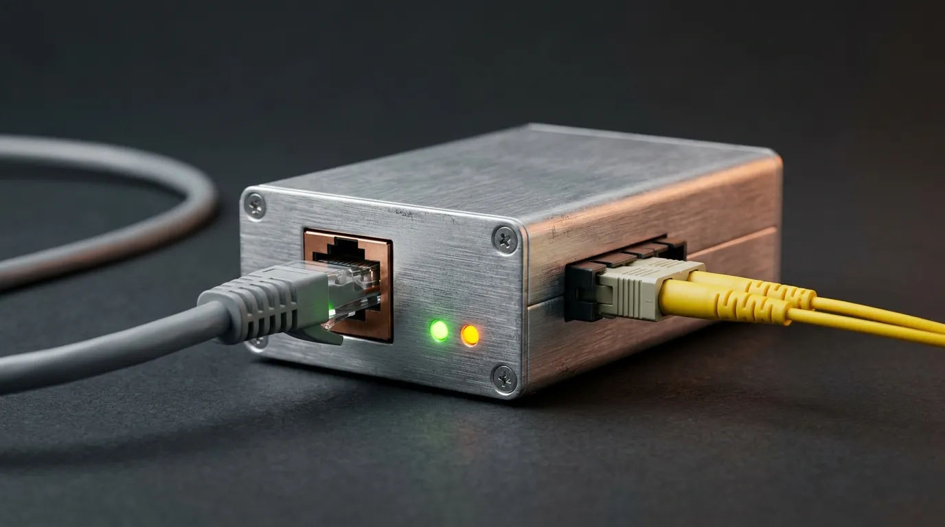
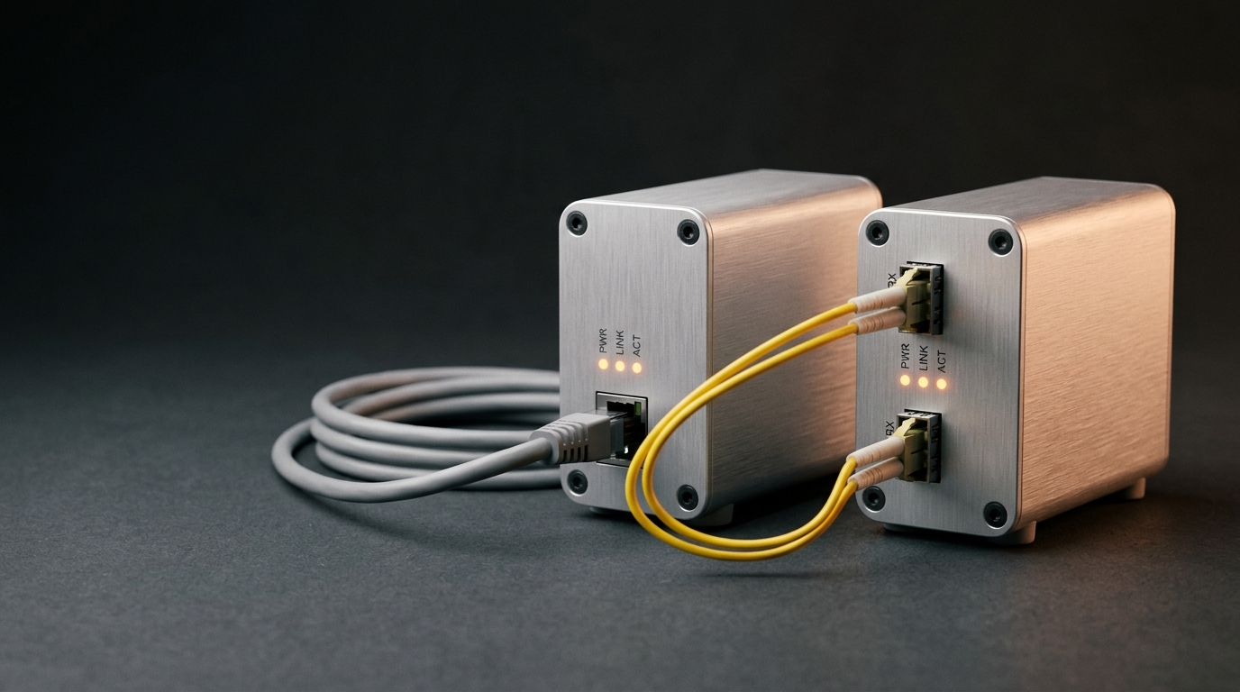
One conversion point: an electrical Ethernet port on one side, an optical fiber port on the other.
There is one deployment rule worth stating up front because it answers the most common question — can a media converter be used without a pair? A converter only ever has one copper side and one fiber side. To connect two copper-only devices across fiber you need two converters, one at each end, sized identically. If the far-end device already has a fiber port (most managed switches do, via SFP), you need only one converter, on the copper end. Converters were introduced for exactly this job in the 1990s: interconnecting fiber-based systems with the copper-based structured cabling that already filled most buildings, as Wikipedia's overview of the fiber media converter notes.
When Fiber Beats Copper — and When a Converter Is the Right Tool
The trigger for this whole discussion is usually distance. The Ethernet physical layer specifications cap twisted-pair links at 100 meters per segment — fine inside a floor, useless across a courtyard, a parking lot, or between two buildings. Fiber has no such practical ceiling at campus scale, it is immune to electromagnetic interference and ground loops between buildings, and it radiates no signal to eavesdrop on. Once a link needs any of those three properties, fiber is the technically correct medium.
But "this link should be fiber" does not automatically mean "buy a media converter." Three alternatives exist, and each wins in specific situations:
- A switch with SFP ports, when you are connecting many copper devices in one place (a whole IDF cabinet, not one camera). The SFP ports are already paid for; adding a converter per device multiplies power adapters and failure points.
- A direct fiber NIC or SFP module in the endpoint, when the device supports it. No extra box at all.
- A media converter, when you have exactly one copper endpoint per location, or when the copper device is old enough that nobody wants to open it for an upgrade.
Converter economics shine on the single-link jobs that campus design is full of — a gatehouse, a security camera pole, a second building on the same site, a legacy switch that still works fine. Those links are the reason campus fiber network design almost always budgets a few converter pairs alongside the backbone cable.
Step 1: Match the Speed Class to the Link
Media converters come in two mainstream speed classes for Ethernet, and the choice is driven by the copper side of the link, not the fiber side.
Fast Ethernet (10/100 Mbps). A 100BASE-FX converter carries 100 Mbps over multimode fiber to roughly 2 km in full-duplex links, per the Fast Ethernet specification. That comfortably covers building-to-building runs, and 100 Mbps is still the honest requirement for most access devices — security cameras, access-control panels, environmental sensors, legacy controllers. If the far-end switch port negotiates 100 Mbps and will never run faster, a fast ethernet media converter is the correct, cheapest answer.
Gigabit (10/100/1000 Mbps). A gigabit converter auto-negotiates with the attached switch and carries 1000 Mbps across fiber. Over multimode fiber with 850 nm optics (1000BASE-SX) the practical limit is 550 meters on high-bandwidth fiber; over single-mode fiber with 1310 nm or 1550 nm optics, links run for tens of kilometers. Gigabit is the default for backbone uplinks, inter-building trunks, and any link you expect to grow.
What about 10G? At 10 Gbps the cost curve changes completely: transceivers cost more than the small converters that house them, and the devices at both ends are almost always modern enough to carry SFP+ directly. Treat 10G as switch-and-transceiver territory, not converter territory.
If your link is… | Order a… | Why |
|---|---|---|
A 100 Mbps access device (camera, controller, sensor) on a short fiber run | Fast Ethernet converter | The far switch port negotiates 100 Mbps; gigabit hardware would negotiate down and buy nothing |
A gigabit switch uplink or building trunk | Gigabit converter (fixed or SFP) | The port is 1G and the link is expected to stay a backbone |
A single-mode run you may light at higher speeds later | Gigabit SFP converter with a single-mode module | Fiber is already in place; changing the module later beats replacing the box |
The practical test for speed class: look at the switch port the converter will plug into. If the port is 10/100, a gigabit converter buys nothing — it will simply negotiate down. If the port is gigabit and the link is a backbone, do not save money with a 100 Mbps converter; the fiber is already in the ground and the next speed bump will not touch it. In TTI Fiber's range, for example, the 10/100 Fast Ethernet media converter covers multimode to 2 km and single-mode duplex links to 80 km, while gigabit media converters use an SFP slot and scale with the module you insert.
Step 2: Choose the Fiber — Single-Mode or Multimode
The converter's optical port must match the fiber already in your cable plant, because you are almost always buying the converter for a fiber run that exists or is being built alongside. Two families matter:
Multimode fiber (OM1–OM5) uses a wider core (50 or 62.5 µm) and short-wavelength optics (850 nm typically, 1310 nm for some 100M links). It is cheaper at the transceiver and the fiber itself, and it is the standard choice inside buildings and data centers where runs stay under a few hundred meters.
Single-mode fiber (OS1/OS2, 9/125 µm) uses a narrow core and 1310/1550 nm optics, reaching 10 to 160 km. It costs a little more at every point, but the fiber itself is future-proof in a way multimode is not — a single-mode run laid today will carry 10G, 40G, and beyond without being replaced.
Link type | Typical fiber | Wavelength | Realistic reach |
|---|---|---|---|
Fast Ethernet, in-building / campus short | Multimode OM3/OM4 | 850 or 1310 nm | 300m or 2 km |
Fast Ethernet, campus long / inter-building | Single-mode OS2 | 1310 nm | 10–80 km |
Gigabit, within a building or floor | Multimode OM3/OM4 | 850 nm (SX) | up to 550 m |
Gigabit, campus / metro | Single-mode OS2 | 1310 / 1550 nm | 10 km to 160 km (with long-reach optics) |
When in doubt between the two, ask one question: will this fiber ever carry more than the current link? If the run is inside one building and shorter than 300 meters, multimode with 850 nm optics is the economical default. If the run crosses a campus, leaves the building, or might be repurposed for a faster backbone later, single-mode vs multimode is a one-sided argument — lay single-mode and let the optics catch up. A single-mode media converter paired with a single-mode run is the combination that turns "we have fiber in the ground" into "we can light any speed on it later."
Step 3: Match Connector and Wavelength — Duplex or Single-Fiber BiDi
A converter is useless if its fiber port does not mate with the patch cord that reaches it. Fixed-port converters typically ship with one of three connector families — SC, ST, or LC — and you should choose the one that matches your existing patch cords and patch panels, or standardize on the connector your cabling contractor uses elsewhere. The fiber optic connector types guide covers the differences; for converters the practical rule is that both ends of a link must present the same connector type and the same optical specifications. Mixing an SC connector on one end and an LC on the other needs a hybrid patch cord and adds a point of failure for no benefit.
The second decision at this step is duplex versus single-fiber (BiDi) operation:
- Duplex converters use two fibers — one transmit, one receive — with identical optics at both ends. Simple, forgiving, and the default for most runs.
- Single-fiber (BiDi / WDM) converters use one fiber for both directions by assigning each end a different wavelength — typically 1310 nm transmit / 1550 nm receive on one end and the mirror image on the other. This halves the fiber count, which matters when you are lighting an existing two-fiber run into a four-fiber need, or when fiber is scarce or expensive to pull. The technique is wavelength-division multiplexing applied to a single strand, and the WDM explainer gives the background.
The trap with BiDi is pairing. BiDi converters ship as A and B units with complementary wavelengths, and the A unit at one end must talk to the B unit at the other. Two A units will never link. When you order single-fiber converters, order them explicitly as matched A/B pairs and label the ends before installation — this is the single most common field error with this product family.
Step 4: Fixed Port or SFP — and How You Power and Manage It
Fixed-port converters have the optics built in: one RJ45, one SC/ST/LC port, done. They are cheaper, smaller, and have one less thing to go wrong. For a permanent point-to-point link whose fiber and distance will not change, a fixed-port unit is usually the right call.
SFP-based converters expose an open slot that accepts a standard SFP transceiver module. You buy the converter once and change the module to change the fiber type, wavelength, or distance — swap a multimode SX module for a single-mode LX, or upgrade reach, without touching the box. If your cable plant mixes multimode and single-mode, or if you expect the link to change, an SFP converter costs a little more now and saves a re-purchase later. This is also the class where management features appear: a gigabit SFP media converter can report digital diagnostic monitoring (DDM) — real-time optical power, temperature, and bias current on the module — which turns a blind remote link into one you can watch from the head end.
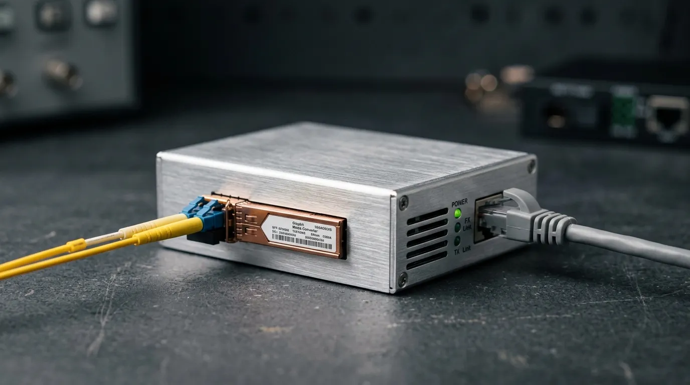
An SFP-based converter: change the module to change the fiber type, wavelength, or reach.
Power is the detail everyone forgets until the first site visit. Standalone converters ship with a small external adapter, and every one of them needs a mains socket or a powered patch bay at both ends — plan the outlets when you plan the fiber. Where the copper endpoint is a device that already receives power-over-Ethernet (PoE), some converters are available PoE-powered (drawing their own power from the injecting switch) or PoE-injecting (feeding a camera on the far end); check the model's capability rather than assuming either direction. For a room full of converters — an MDF, an IDF, an ISP aggregation node — a rack-mount chassis powers many converter cards from one redundant supply and lets you mix Fast Ethernet and gigabit cards in the same shelf, which beats a drawer of wall warts on every axis: power resilience, heat, and cable management.
If the far end of a link is genuinely remote — a gatehouse, a roadside cabinet, an industrial enclosure — prioritize two things: a converter with link-loss propagation (so a dead fiber drops the copper link too, and the far device's alarm actually fires) and one whose operating temperature range suits the enclosure. Industrial-temperature converters are rated for −40 °C to +85 °C and are the correct choice for unheated outdoor cabinets, as covered in our industrial fiber optic cable guide.
Step 5: Buy a Matched Pair and Plan It as Part of the Cabling System
Ordering discipline prevents most field failures, and it starts with the word pair:
- Fixed-port links: order two identical units — same speed, same fiber mode, same wavelength, same connector. One goes at each end.
- BiDi links: order one A and one B unit and record which end gets which.
- Order the patch cords and adapters in the same PO — a converter with no LC-to-LC patch cord on the day of install is a converter that does not work.
- Do not mix multimode and single-mode optics across a link; the fiber, both converters, and both modules must agree on mode.
- Keep spare units in the same spec as the deployed ones. A mixed drawer of spare converters is how a 2 a.m. swap becomes a duplex-mismatch outage.
Where the converters physically live is a cabling-system decision, not a device decision. In a classic layout the fiber backbone terminates on patch panels in the MDF and IDF rooms, and the converters sit next to those panels, converting backbone fiber down to copper for the local switches. The patch-cord discipline from the fiber side applies here too: a clean, labeled patch between panel and converter makes the pair trivially serviceable, while a rat's nest of uncut cords is where "it worked yesterday" problems are born. For deployments with many links — fiber to the desktop rollouts included, where converters sit at each desk's copper outlet — the rack-mount chassis version of this step is what keeps the room serviceable at scale.
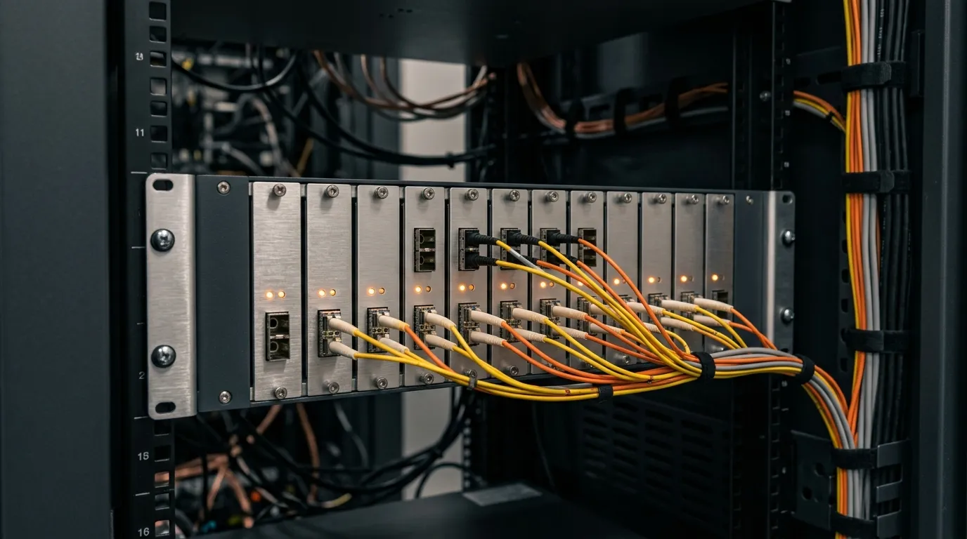
A chassis centralizes power and management when one location terminates many converter links.
Step 6: Install, Verify, and Troubleshoot
Installation itself is plug-and-play — that is the point of the device — but verification follows a fixed order so that a fault is found in minutes, not hours:
- Check the power LEDs first. Both converters must be powered before anything else is true.
- Check the fiber-side link LED at both ends. Dark on one end and lit on the other usually means a bad or reversed fiber — duplex pairs must land TX-to-RX on the far side.
- Check the copper-side link LED. If fiber is up but copper is down, suspect the cable or the far switch port, not the converter.
- Confirm speed negotiation matches what you intended. A gigabit link that negotiated down to 100 Mbps still passes traffic — and still quietly halves your backbone. Check the switch port's negotiated speed after link-up.
- Clean before you blame. Dirty connector end-faces are the leading cause of marginal optical links, and the fix is a one-minute wipe with a proper cleaner, not a replacement converter. Treat the connectors on the patch cord and the converter port as the fragile precision parts they are.
The failure patterns that send people back to the vendor are almost always one of five: a single-fiber A/A (or B/B) mismatch; a duplex pair crossed; a multimode/single-mode mismatch somewhere in the chain; a speed-class mismatch with a switch port that cannot negotiate what the converter expects; or a power problem at one end that no LED check was ever going to reveal from the other side. Every one of these is caught by the five checks above before you ever call support.
The Ordering Checklist
When you send a request for quotation, a complete converter spec has exactly seven lines. Fill them in and the supplier cannot guess wrong:
- Quantity of converter pairs and whether any single-fiber (A/B) pairs are included
- Speed class: Fast Ethernet or Gigabit
- Fiber mode: multimode or single-mode, and the fiber core size
- Connector: SC, ST, or LC (fixed-port models)
- Reach: expected link distance, so long-reach optics are quoted when needed
- Power: external adapter, PoE, or chassis card
- Environment: indoor standard, or industrial temperature range
If this guide leaves you with one habit, make it this: decide the six steps on paper before opening a catalog. The fiber optic media converter page on our site shows the Fast Ethernet and gigabit families built to the specs above — standalone or chassis-mounted, standard or industrial temperature, with OEM and ODM options for projects that need their own branding. And when the converter is part of a larger backbone project, start from the structured cabling hub so the boxes, the cable, and the panels are designed as one system instead of three purchases.