Substation Fiber Optic Cabling Guide
Why Substation Fiber Optic Cabling Runs on Glass
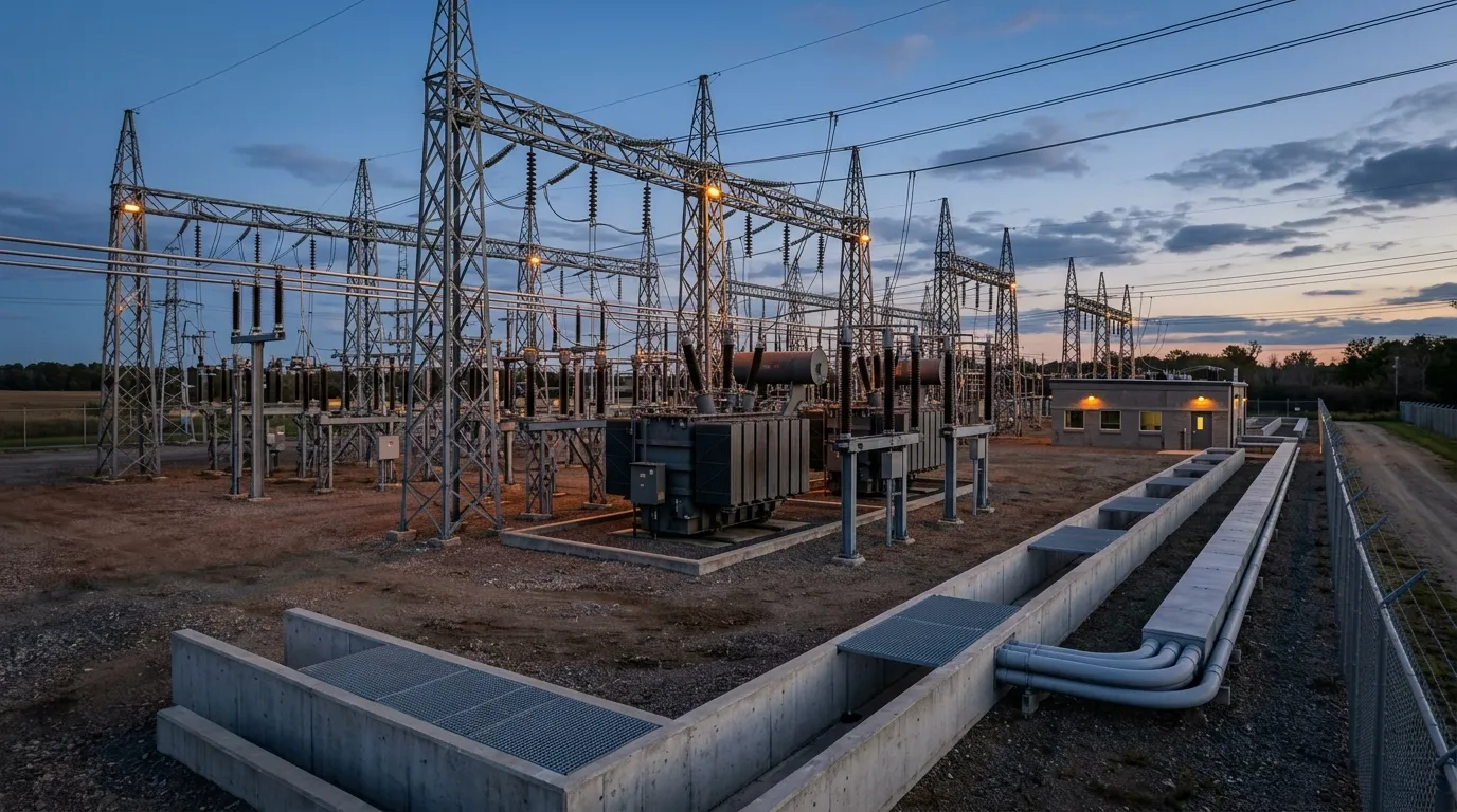
A substation is one of the least friendly places on the grid for a communications link. Switching transients, fault currents, corona discharge and radio-frequency interference fill the air with electrical noise, and a copper link sitting next to energized equipment picks up exactly the wrong kind of signals. Hardwired copper circuits also run into a distance ceiling: Qualitrol's engineering note on fiber optics in substations puts the practical limit for hardwired links at roughly 150 meters before noise and voltage rise become a real problem.
Fiber optic cable sidesteps both issues. Because the signal travels as light through glass, fiber is immune to electromagnetic interference, and an all-dielectric link provides electrical isolation between the devices it connects — protection relays, bay controllers, and monitoring equipment that would otherwise share a dangerous ground path. That isolation is exactly what modern substation automation demands.
The driver behind most substation fiber optic cabling projects today is IEC 61850, the standard family for substation communication networks. Protection and control messages, sampled values and GOOSE trips all move over the station network with latency budgets measured in milliseconds, and protection-grade traffic cannot tolerate the noise-induced retries a copper path may suffer under a switching surge. Copper can carry some of that traffic, but fiber is the reliable default for the station bus, and it is essentially mandatory where long runs, yard-to-control-room hops, or high-integrity protection paths are involved.
The operating environment makes the choice stick. Outdoor switchyard equipment endures the full temperature range of the site, direct sun, moisture, and the vibration of nearby switchgear operations, and the control-room side has its own constraints — fire ratings, tray routing, and limited space in relay cabinets. Fiber optic cable handles the temperature and EMI side of that equation gracefully, which is one more reason utilities stopped debating the technology and moved on to the details of doing it well.
The question is no longer whether to use fiber in a substation. It is how to specify, route, terminate and protect it so the link outlives the maintenance cycle instead of becoming a chronic trouble ticket.
What a Substation Fiber Network Looks Like
Before picking cable, map the network you are building. A typical IEC 61850 station network has three layers, described in more detail in the IEC 61850 overview on Wikipedia:
- Station bus — the control-room backbone connecting the SCADA/HMI, engineering workstation, time-sync source and gateway to the bay-level IEDs.
- Process bus — the high-speed link carrying sampled values and GOOSE between merging units in the yard and protection relays, often with strict latency and redundancy requirements.
- WAN/uplink — the connection out of the station to the utility's control center, usually riding OPGW, ADSS or leased fiber from the nearest ring.
Inside the fence, most of the fiber is singlemode. A single-mode vs multimode comparison is worth reviewing if the design team is tempted by multimode's lower transceiver cost, but for substation runs — yard distances, future bandwidth growth, and long-haul uplinks — G.652D singlemode fiber is the safe, common choice.
Fiber count planning deserves attention at the architecture stage. A small 110 kV substation might need a dozen active fibers for protection, control and metering; a large EHV station with redundant process buses and sampled-value links can need several times that, because process-bus redundancy often doubles the protection fibers by design. A conservative rule used by many utilities: size the cable for current needs, then add dedicated spare tubes or 30–50% spare fibers so a failed splice, a damaged section, or a future IED doesn't force a re-pull. Every fiber that is terminated in the control room ends at a patch panel or ODF — that is where the network is actually operated from, and where spare fibers become usable capacity.
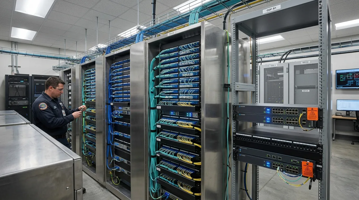
Every terminated fiber in a substation ends at a patch panel or ODF in the control room, where the network is actually operated.
Choosing Cable for Each Substation Zone
Substation fiber optic cabling is really three separate installations in one. Split the design by zone and each zone has a clear cable family:
Zone | Environment | Recommended cable | Why |
|---|---|---|---|
Control room / building | Indoor, fire-safety regulated, tight bends | Indoor tight-buffered, LSZH jacket, riser-rated | Low smoke/halogen in occupied spaces; small bend radius for trays and racks |
Switchyard — duct or buried | UV, moisture, crushing, rodents, vehicle traffic | Outdoor loose-tube; steel-tape armored (GYTA53-class) for direct burial or trench; anti-rodent glass-yarn types in rural/perimeter runs | Mechanical protection where maintenance vehicles and animals roam |
Yard-to-tower aerial approach | High-voltage proximity, lightning | ADSS (all-dielectric self-supporting) or OPGW on the transmission side | No metallic members = no induced voltages or ground loops |
Fence line / perimeter | Rodents, vandalism, ground pressure | Armored or anti-rodent construction, buried in duct | Rodent damage is one of the most common failure modes |
The aerial question deserves its own decision point. The FOA's reference on fiber for electrical utilities walks through the full family — ADSS, OPGW, OPPC and OPAC — and when each is used. For substation approaches on utility-owned lines, the practical choice is usually:
- ADSS — fully dielectric, self-supporting, spans without a messenger, and safe to hang in the vicinity of energized conductors. The trade-off is span-length and sag engineering.
- OPGW — a ground wire with fiber in its core, used when the approach is part of the transmission line itself. It replaces the shield wire, so it is a line-engineering decision, not just a cable decision. Our ADSS vs OPGW comparison covers the boundary and the decision criteria in detail.
- Figure-8 cable — the cost-effective self-supporting option on lower-voltage distribution lines where ADSS engineering is overkill.
For the switchyard itself, the cable family matters more than brand. Outdoor armored fiber optic cable types explains the GYTA/GYTS/GYTA53 families: steel-tape armored loose-tube cable (GYTA53-class) for direct burial and trench runs, non-metallic FRP-core types (GYFTY/GYHTY) where you want dielectric construction near HV equipment, and glass-yarn anti-rodent layers for perimeter segments. Rodent protection is not a luxury in rural substations — cable runs along fence lines and through grass are the most attacked sections.
For a deeper look at how cable construction — buffer type, strength members, armor, jacket — behaves in industrial environments, browse our industrial fiber optics hub and the industrial fiber optic cable guide it links. If you are building a substation project on a budget, TTI Fiber manufactures the whole outdoor family — ADSS, GYTA53-class armored, non-metallic and anti-rodent types, all in G.652D with attenuation of ≤0.36 dB/km at 1310 nm — with factory-direct OEM/ODM support, and ADSS specifications are on the product page if you need numbers to work with.
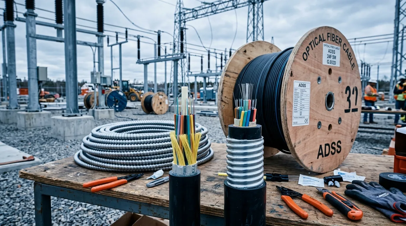
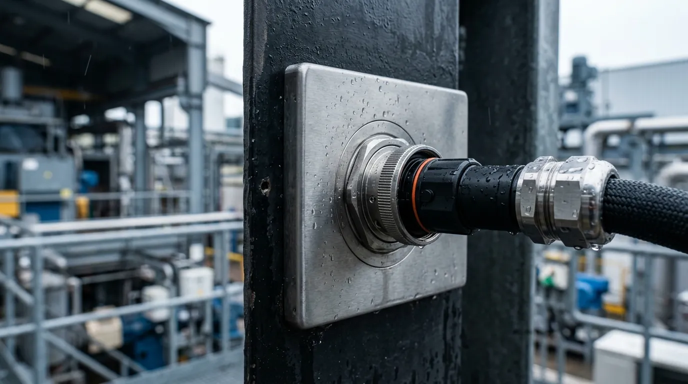
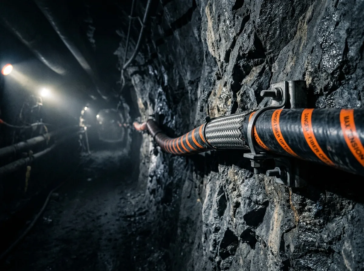
The two workhorses of substation cable selection: all-dielectric ADSS for aerial approaches and armored outdoor cable for the yard.
Routing Fiber in the Yard: Ducts, Trays, and Separation
The route plan decides most of your future reliability. Three rules dominate substation fiber optic installation:
1. Keep fiber out of power-cable runs. Fiber must not share a duct, trench or conduit with power cables. In cable trays, run fiber in a separate tray or on a divided section above power trays — this is not cosmetic: fault currents in power cables can induce voltages in adjacent metallic members, and a shared trench makes cable replacement and identification miserable. Separation distances vary with voltage class and local utility practice, so design to your company's standard and the relevant IEC utility cabling guidance, and record the ruling values on the drawings.
2. Manage bends and tension at every step. Loose-tube outdoor cable is engineered for straight-ish routes: keep bends to at least 20× the cable diameter while pulling and 10× once installed, and stay under the cable's rated tension (typically no more than 70–80% of the spec maximum during pulls, less around corners). The 101 Guidelines for Fiber Optic Cable Installation from Fiber Optics 4 Sale is a solid checklist for pulling grips, lubricant use, and avoiding kinks. The most common silent killer is a too-tight bend at a tray corner or a cable entry point — it passes the pull, then shows up years later as an OTDR anomaly.
3. Choose duct over direct burial where you can. Inside a substation, concrete-encased duct banks or HDPE ducts cost more up front and pay for themselves in repair-ability: a damaged section can be re-pulled instead of re-buried, and expansion is a pull away. Where direct burial is unavoidable — perimeter segments, long fence-line runs — use armored cable, proper depth, and warning tape; our underground fiber optic cable guide covers burial depth and backfill practice in detail.
Add slack at both ends of every section (a service loop at the closure and at the ODF), and keep the drawing updated with duct IDs, tray paths and pulling section lengths. As-built accuracy is what makes a future repair possible.
Two yard-specific routing details are worth calling out. First, in cable trays, fiber should sit on its own tray tier above power trays with a solid divider or dedicated tray — not just "sort of separated." When trays are full, resist the temptation to lash fiber to the underside of a power tray; it saves a tray today and guarantees an induced-voltage or access problem tomorrow. Second, at equipment foundations and cable entries into junction boxes and marshalling kiosks, protect the cable against chafing on concrete edges — a short length of conduit or grommeted entry fitting at every penetration is cheap insurance against vibration wear over decades of service.
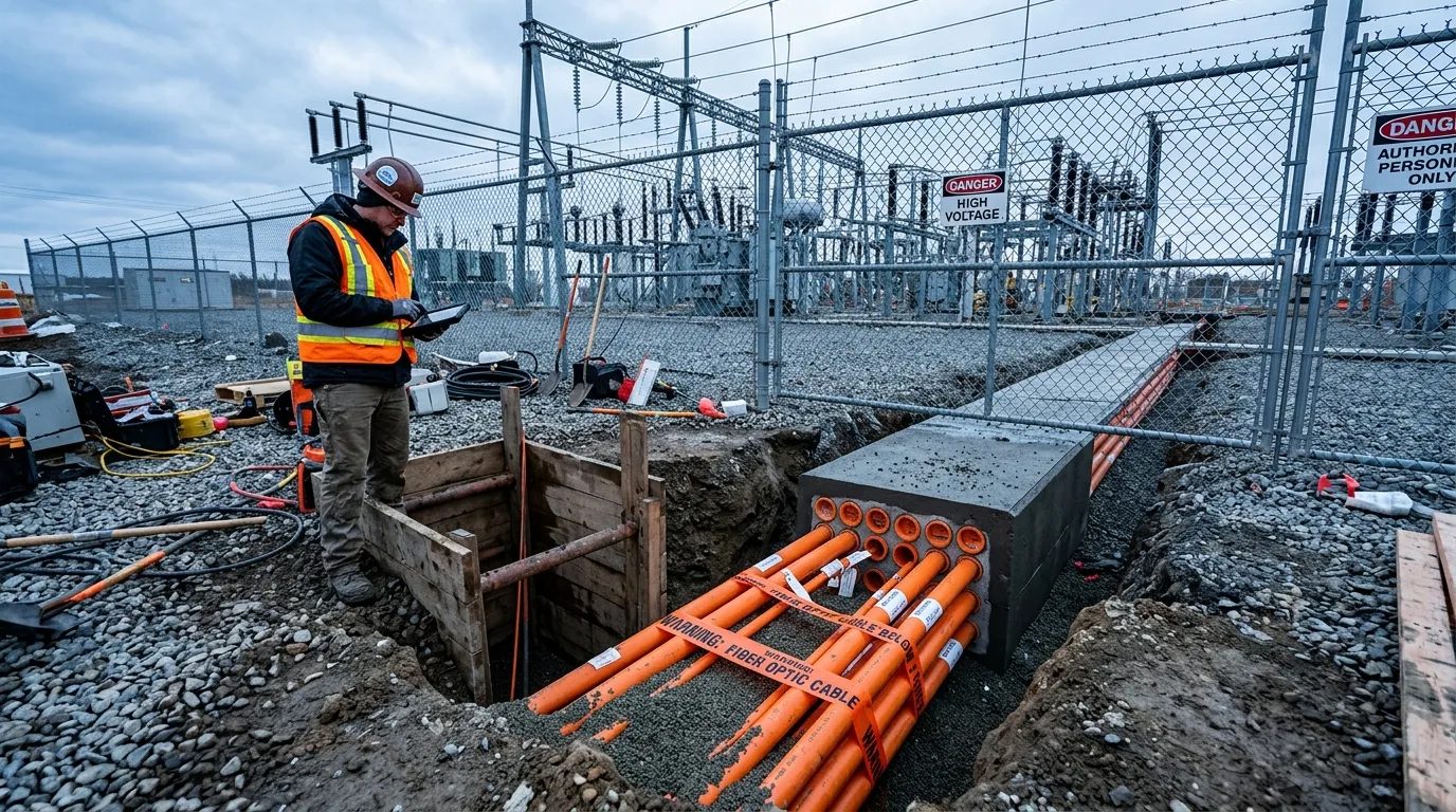
Duct banks give substation fiber routes the repair-ability that direct burial cannot: damage is a re-pull, not a re-bury.
Splicing, Termination, and the Indoor-Outdoor Transition
Fusion splicing is the reliability-critical skill in substation fiber optic cabling. A good singlemode fusion splice lands at 0.03–0.05 dB loss — anything much above that is a red flag worth re-doing. Every splice goes into a splice tray inside a closure, protected by a splice sleeve, with the fiber coiled to the tray's minimum radius.
Where closures go matters as much as how they are spliced:
- In the yard, closures mount on walls, poles, or in below-grade vaults. Use IP68-rated enclosures with proper cable sealing (gel blocks or heat-shrink), water-blocking where moisture is a risk, and leave a generous service loop — re-entry happens, and a closure without slack cannot be re-spliced. The aerial vs underground splice closure comparison helps with the mount decision.
- At the building entry, the indoor-outdoor transition is where moisture and fire-stopping failures happen. Penetrations must be sealed both for water and for fire rating, and the outdoor cable should be terminated or transitioned inside the building at a demarcation point — never spliced in a damp basement corner. AFL's engineering webinar on the transition of fiber optic cable into substations is a good reference for real-world entry designs.
- At the control room, trunk fibers terminate at an ODF or patch panel via fusion-spliced pigtails, and jumpers (patch cords) complete the path to the relays and switches. Terminate every fiber you pull, label both ends and the panel ports, and test the jumpers — untested patch cords are a classic source of "mystery" link failures.
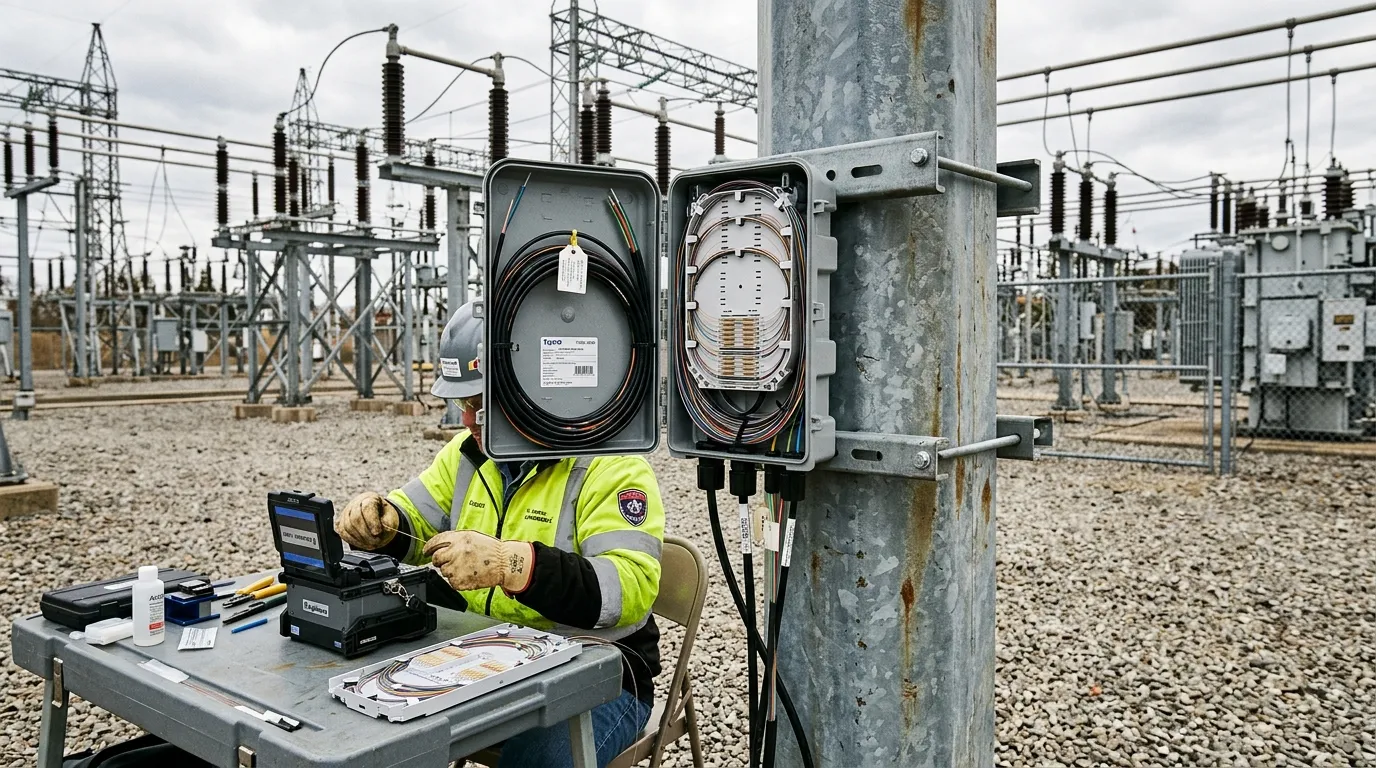
Closures in the yard must be IP-rated, properly sealed, and left with a service loop — re-entry happens.
Grounding, Surge, and Lightning: Dielectric Isn't Optional
This is the section where substation fiber cabling stops being a telecom job and becomes a power-systems job. IEEE 1613, the standard for communications networking devices in electric power substations, exists precisely because substation-grade equipment must survive the EMI environment — and the cabling you install is part of that environment.
The cleanest way to eliminate surge and grounding problems is to not have metallic members in the first place. All-dielectric cables — ADSS in the air, FRP-core GYFTY/GYHTY in the yard — contain no armor, no messenger and no steel strength member, so there is nothing to induce a voltage into and nothing to ground. That is the main reason dielectric construction is the default recommendation near energized equipment.
If the design calls for steel-tape armored cable (crush and rodent protection), the armor is a metallic member and must be treated accordingly:
- Bond and ground armor at defined points per utility practice, typically at the building entry and at closures.
- Avoid creating ground loops — armor continuity through a closure should be a deliberate decision, not an accident.
- Coordinate the grounding plan with the station ground grid and the protection engineer before installation, not after a trip event.
A common misconception is that "fiber is non-conductive, so grounding doesn't matter." The glass is non-conductive — the hardware around it (closures, trays, patch panels, armor) is not, and it sits inside the station's equipotential zone. Treat the whole fiber path as part of the station grounding system and you will never have a surprise.
Testing and Commissioning the Installed Link
Installation is not complete until the link is measured and documented. A pragmatic commissioning sequence:
- Visual inspection — every connector endface checked under a scope before mating; contamination is the #1 cause of field failures.
- OTDR testing, both directions — event maps confirm splice loss, connector loss and any damage from the pull. Bidirectional testing separates real loss from measurement artifacts on long runs.
- Insertion loss and return loss — measured end-to-end per link, compared against the calculated loss budget (cable attenuation + connector losses + splice losses + margins).
- Documentation — OTDR traces archived, as-built drawings updated, fiber labels verified, and the loss budget sheet signed off.
A typical budget sheet for a short substation link looks like this:
Budget item | Typical value | Units |
|---|---|---|
Cable attenuation (G.652D @1310 nm) | 0.36 | dB/km |
Fusion splice (each) | 0.03–0.05 | dB |
Connector pair (LC, each mated pair) | 0.3–0.5 | dB |
Patch cord and ODF routing margin | 0.5–1.0 | dB |
Design margin for aging and future splices | 2–3 | dB |
For a 500 m link with four splices and three connector pairs, the budget lands around 2–3 dB before margin — well inside the typical 10 dB power budget of a standard singlemode transceiver. If the measured link is close to or above the calculated budget, hunt the excess before accepting the job.
The acceptance criterion is simple: measured link loss must be within the calculated budget, typically with margin for aging and future splices. If a link fails, fix it now — commissioning failures become expensive truck rolls later. For long or critical protection paths, keep the bidirectional OTDR traces on file with the station documentation: when a fiber degrades years from now, the baseline trace is what tells the maintenance crew whether the problem is a splice, a connector, or a cable section. Testing is not a formality; it is the only moment you can prove the installation is sound before the station depends on it.
Common Substation Fiber Cabling Mistakes
Eight failures account for most substation fiber optic cabling problems in the field:
- Sharing a duct or trench with power cables — induced voltages, hard maintenance, and code trouble.
- Bend-radius violations at tray corners and entries — silent damage that only shows up on OTDR years later.
- No spare fibers or spare tubes — every future IED means a re-pull.
- Ignoring rodent risk at the perimeter — armored or anti-rodent cable is cheaper than a failed link at 3 a.m.
- Metallic armor with no grounding plan — an induced-voltage liability inside the yard.
- Poor indoor-outdoor sealing — moisture finds the splice tray eventually.
- Skipping OTDR acceptance testing — undocumented links are unmaintainable links.
- Terminating every fiber except the spare — spares only work if they are spliced, tested and labeled.
FAQ: Substation Fiber Cabling Quick Answers
Can fiber optic cable run alongside power cables? Not in the same duct or conduit, and not in the same tray section. Route fiber in separate ducts and separate or divided trays, and follow your utility's separation rules for the voltage class.
How many fibers do I need in a substation? Count active needs (protection, control, monitoring, metering, uplink), then add spare tubes or 30–50% spare fibers. Undersizing fiber count is the most expensive cable decision to reverse.
ADSS or OPGW for the approach? For a substation approach on an existing distribution line, ADSS is usually the simpler choice — dielectric, self-supporting, no line-engineering changes. OPGW makes sense when the fiber path is part of a transmission line's ground wire system.
Duct or direct burial inside the substation? Duct where repair-ability matters (most places inside the fence); armored direct burial for long perimeter segments where ducts are impractical.
Do I need armored cable inside the substation? In switchyard and perimeter runs, yes — vehicles, rodents and ground pressure make unarmored cable a gamble. In the control room, indoor tight-buffered cable is sufficient.
Getting the Cable Right: Next Steps
Substation fiber optic cabling rewards a systematic approach: map the IEC 61850 network first, select cable by zone, route with separation and bend control, splice and terminate with documented quality, and test everything before handover. None of the steps is exotic — but skipping any of them shows up in the outage log.
When you are ready to spec the cable, TTI Fiber manufactures the full outdoor family used in these designs — ADSS for aerial approaches, GYTA53-class armored cable for direct burial, non-metallic FRP-core types for dielectric runs, and anti-rodent constructions for perimeter protection — all in G.652D singlemode with factory-direct OEM/ODM support. Request a quote with your fiber count, route distances and zone breakdown, and the engineering team will help you size the right drum.