High Temperature Fiber Optic Cable Guide
A cable tray 400 mm from a furnace roof is not a data center. Heat there is radiant, uneven, and present every hour of the plant's life, and the cable you hang in it has to hold its attenuation for fifteen years, not for the length of a commissioning test.
A high temperature fiber optic cable is not one product with one rating; it is a construction whose weakest layer sets the ceiling. This guide is about transmission cable for hot locations — steel and foundry, cement, boiler houses, substation trenches, downhole. It is not about fiber optic temperature sensors, which are a different product with a different job. If you are specifying a cable to carry data through a hot zone, the decision has four layers: coating, jacket and buffer, construction, and termination. Each has its own temperature limit, and the cable is only as good as the lowest one.
What Counts as High Temperature (and Why +85 °C Is the Ceiling for Standard Cable)
"High temperature" is not one regime. In practice, fiber cable falls into four bands, and each band is limited by a different component.
Band | Ambient | Typical construction | What limits it |
|---|---|---|---|
Standard | −40 °C to +85 °C (−40 °F to +185 °F) | PE or PVC (both ≈+80 °C) or LSZH jacket; dual-layer acrylate coating; gel-filled loose tube | The acrylate coating and the thermoplastic jacket |
Extended | +85 °C to +125 °C (185 °F to 257 °F) | High-temperature cross-linked LSZH or PUR/TPU; dry or ePTFE buffer; high-temperature acrylate fiber | The jacket compound |
High temperature | +125 °C to +200 °C (257 °F to 392 °F) | Silicone, FEP or PTFE jacket; ePTFE tape or metal tube; high-temperature acrylate or polyimide fiber | Buffer system and coating |
Extreme | +200 °C to +400 °C (392 °F to +752 °F) | PTFE/PFA jacket, stainless steel tube, polyimide-coated fiber | Termination and handling, not the glass |
Between +105 °C and +125 °C there is no commodity thermoplastic in the material table further down — an ordinary LSZH stops near +90 °C and an ordinary PUR near +105 °C. That gap needs a qualified specialty compound. Above it, the practical step is a fluoropolymer: FEP is rated around +200 °C and extrudes like a normal jacket, so it covers the +125 °C to +180 °C stretch, where silicone only just begins. The same arithmetic applies at the bottom of the table: PE and PVC top out around +80 °C, so the +85 °C figure is the coating's ceiling and needs an LSZH or a higher-rated compound on the outside of it.
The glass itself is not the problem. Fused silica softens at about 1,585 °C; a standard telecom fiber will happily carry light at temperatures no polymer in the cable could survive. Everything you are really selecting is the packaging.
Three numbers have to be stated separately, and most datasheets blur them:
- Continuous operating temperature — the ambient the cable is designed to sit in for its service life. This is the number you design to.
- Short-term or intermittent temperature — an excursion the cable survives without permanent change, usually for hours, not years. Useful for a furnace reline, a blocked cooling fan, a startup transient.
- Installation and storage temperature — always narrower than the operating range. A cable rated to +200 °C may still be limited to +50 °C while you are pulling it, because the jacket is being bent and dragged, not just sitting there.
A cable sold as "rated to 200 °C" without those three numbers is telling you one third of what you need. The general industrial rating — −40 °C to +85 °C — and how it is verified is covered in our guide to how temperature changes affect fiber performance; this article starts where that one stops.
How Heat Actually Degrades a Fiber Link
Five mechanisms do the damage, in roughly this order of frequency.
1. Differential expansion, then microbending. Fused silica expands at about 0.5 ppm/°C. The polymers around it expand at 50 to 300 ppm/°C — two orders of magnitude more. Above the jacket's glass transition the compound grows faster than the fiber can follow, and wherever the fiber is coupled tightly enough to be pushed sideways, it micro-bends. Microbends do not break the link; they add loss, a few tenths of a dB per kilometer at a time, and the loss moves with temperature, so the fault looks intermittent.
2. Buffer tube shrinkage and fiber protrusion. A loose tube contracts as it cools, and if the fiber is not free to slip, it is dragged with the tube. The result is fiber pushed out of the tube end inside a splice closure — the standard IEC test for this is a cable shrinkage test precisely because it is common. In the other direction, hot gel filler flows and drips out of an upward-facing tube end, leaving the fiber unsupported and water-blocking gone.
3. Jacket softening, then embrittlement. Thermoplastics lose modulus well before they melt. A jacket that has gone soft will creep under cable ties and crush loads, ovalize the core, and squeeze the fiber. Years later the same compound has oxidized and embrittled, so the next time someone opens the tray the jacket cracks instead of flexing, and moisture gets in through a crack nobody sees.
4. Coating degradation. The protective coating on the fiber is a polymer too, and it is the closest polymer to the glass. Standard acrylate is designed for the −40 °C to +85 °C world; pushed above that it oxidizes and hydrolyzes, strip force climbs, and the fiber's proof-tested strength is no longer what the datasheet promised.
5. The termination fails first. Connectors, adapters, boots and the epoxy that holds the ferrule are almost always rated narrower than the cable — commonly −40 °C to +85 °C for field-installable parts. A hot zone with twenty connectors has twenty components that were never designed for it, and they are at the end of the link where nobody re-measures after the first summer.
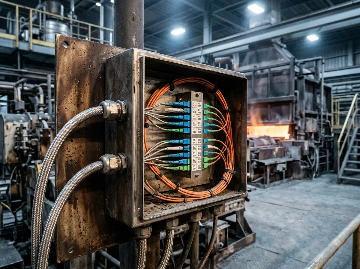
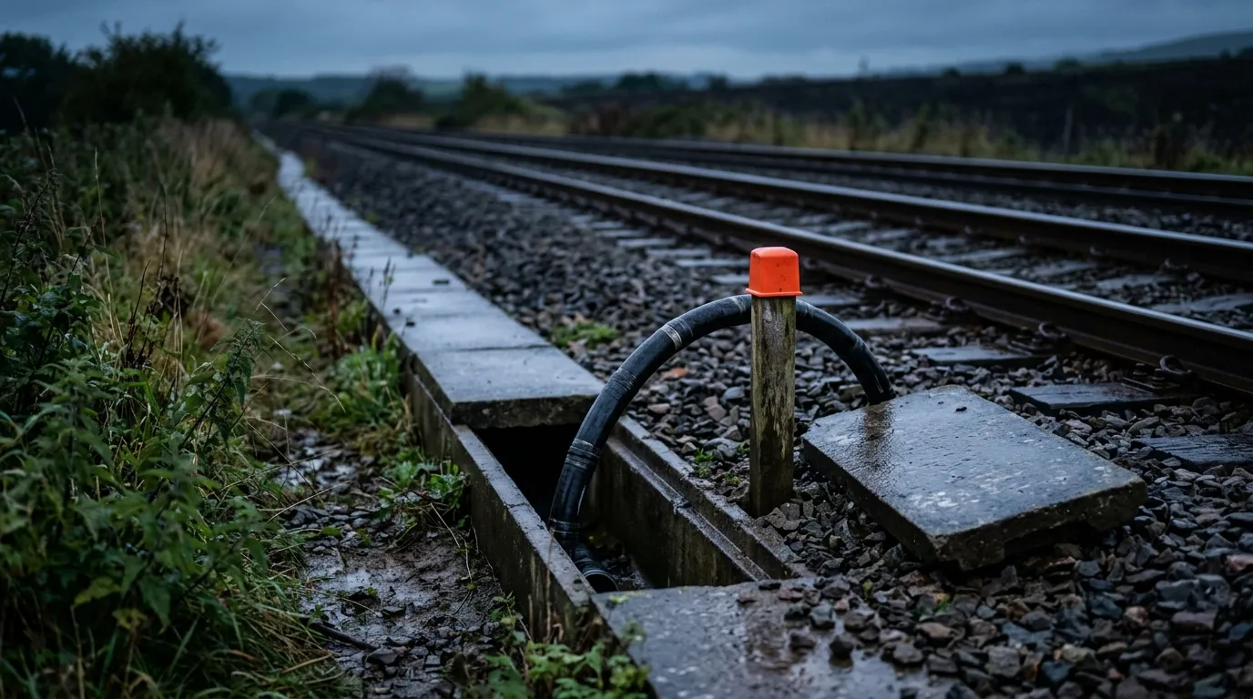
Illustrative image. The connector is usually the first thing to fail in a hot zone — most field terminations are qualified to +85 °C, well below the cable behind them.
Every one of these mechanisms shows up first as loss, not as a fault. The link still passes traffic, the dashboard still says "up", and the only evidence is a few tenths of a dB that nobody measures again — which is why a high-temperature route has to be tested, not just inspected.
We cover the full industrial selection framework in the industrial fiber optic cable guide; the rest of this article keeps to the heat-specific decisions.
Layer 1 — The Coating Sets the First Limit
Before you choose a jacket, choose the fiber's coating, because no jacket can protect a coating that is already outside its range. Dual-layer acrylate is the default on every standard single-mode and multimode fiber, and it is rated to about +85 °C; above that, coating suppliers are explicit that acrylate is not adequate for long-term exposure. Three coatings cover the rest of the range.
Coating | Typical continuous | Short excursions | Handling implications |
|---|---|---|---|
Dual-layer acrylate | +85 °C | ~+100 °C | The default. Field-strips and cleaves easily |
High-temperature acrylate | +150 °C | +200 °C | Same handling as standard acrylate; characterized in published 150 °C design-verification work |
Polyimide | +300 °C | +350 °C | Polyimide fiber data: 155 µm coated diameter over a 125 µm cladding, brittle, needs polyimide-rated stripping tools and a trained crew |
Carbon/hermetic over polyimide | +300 °C and above | — | Adds hydrogen and moisture protection for downhole and subsea |
If your continuous temperature is above +150 °C, the fiber coating decision drives everything downstream — including whether the cable can be terminated in the field at all.
Layer 2 — Jacket and Buffer: The Material Temperature Table
This is the part most spec sheets leave out. The jacket compound sets the cable's continuous rating, and the buffer sets whether the fiber is mechanically protected at that temperature.
Material | Typical continuous | Short excursions | Where it fits — and what it costs you |
|---|---|---|---|
PVC | +70 to +80 °C (158 °F to 176 °F) | ~+105 °C (221 °F) | Cheapest, flame retardant, easy to process. Plasticizer migrates with age and heat; the jacket hardens and cracks |
PE (MDPE/HDPE) | +70 to +80 °C (158 °F to 176 °F) | — | Best moisture barrier per dollar, good UV with carbon black. Flammable; not for indoor or confined spaces |
LSZH | +80 to +90 °C (176 °F to 194 °F) | ~+120 °C (248 °F) | Low smoke, halogen-free, required in tunnels and occupied spaces. Heavily filled, so stiffer and more moisture-sensitive |
PUR (TPU) | +90 to +105 °C (194 °F to 221 °F) | ~+125 °C (257 °F) | Abrasion and cut resistance, flexible in cold. Costs more; limited UV life unless stabilized |
Silicone rubber | +180 to +200 °C (356 °F to 392 °F) | ~+250 °C (482 °F) | Stays flexible when hot, good dielectric. Low tear strength, high permeability to water vapor, expensive |
FEP | ~+200 °C (392 °F) | ~+230 °C (446 °F) | Melt-processable fluoropolymer: extruded like a normal jacket, chemically inert |
PFA | ~+260 °C (500 °F) | ~+280 °C (536 °F) | As above with a higher ceiling; the most expensive extrudable option |
PTFE | −200 to +260 °C (−328 °F to +500 °F) | — | The reference high-temperature jacket. Applied as tape wrap and sintered rather than extruded, so it is stiff, seam-sensitive and hard to strip |
ePTFE tape buffer | not a material limit — see note | — | Porous expanded PTFE used as the buffer/binder layer; light, crush-tolerant, and it does not flow like gel. Expanded PTFE is still PTFE, so the +135 °C in the GORE assembly below is that cable's rating, not this tape's ceiling |
Stainless steel tube | +400 °C and above (752 °F and above) | — | The answer above ~+250 °C. Stiff, heavy, needs grounding and a termination plan; not a field-terminable cable |
Two cautions on reading that table. First, these are typical catalog continuous ratings for the material family — a specific compound from a specific supplier may be better or worse, and the cable datasheet, not the polymer data sheet, is what you are buying. Second, the rating belongs to the assembly. A PTFE jacket over a standard acrylate fiber is an 85 °C cable wearing an expensive coat. Fluoropolymer performance is documented by the material makers — Teflon fluoropolymers are rated from −200 °C to +260 °C — and expanded PTFE buffering is what makes aerospace cable practical: GORE's 1.8 mm simplex datasheet lists a −65 °C to +135 °C range on a PFA jacket, high-temperature acrylate coating and ePTFE buffer (GORE fiber optic cable datasheet). The cable's number is the minimum of every layer, plus the test that proved it.
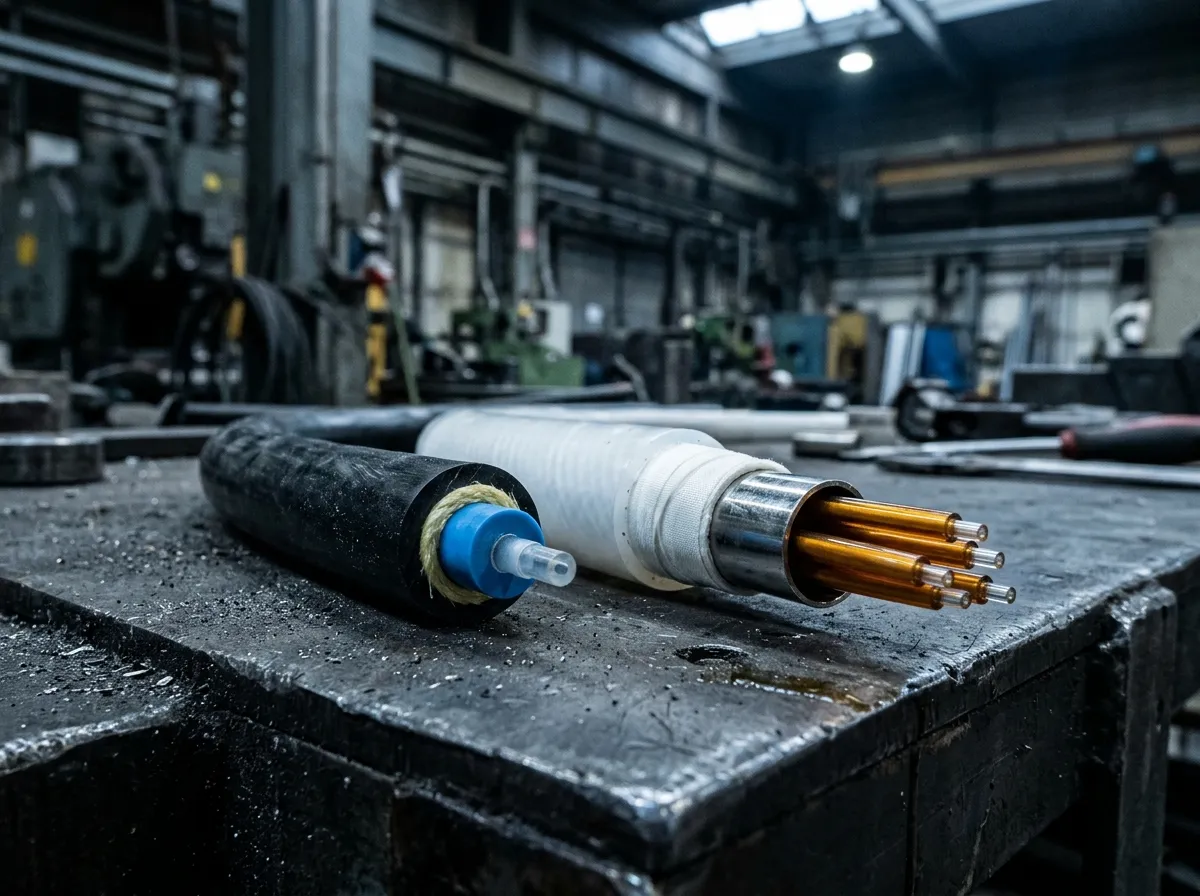
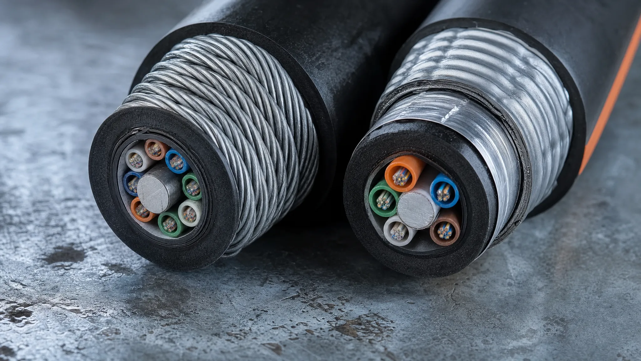
Illustrative image. Left: a standard PVC-jacketed cable stripped to its blue tight buffer and acrylate-coated fiber — a −40 °C to +85 °C assembly. Right: a high-temperature construction with a wrapped fluoropolymer jacket, ePTFE tape and a stainless steel tube. The temperature rating is set by the weakest layer, not by the jacket alone.
Buffer construction follows the same logic. Gel-filled loose tube is excellent to +85 °C and becomes a liability above it, because the filler flows; dry, swellable or ePTFE buffer systems avoid the migration problem. Tight-buffered cable is easier to terminate and better in short runs and patch cords, but the buffer is in direct contact with the fiber, so expansion has nowhere to go — it is the wrong choice for long hot runs. The trade-offs between the two are covered in our tight-buffered vs loose-tube comparison.
Layer 3 — Build the Construction for the Route, Not the Datasheet
A cable's temperature rating is measured in still air. A plant route is not still air.
Measure the surface, not the room. Radiant heat from a furnace wall, a steam line or a ladle can put a cable's jacket tens of degrees above the surrounding air. An infrared thermometer on the tray at the hottest hour of the shift is the number that matters; ambient temperature in the aisle is not. If you cannot get the surface figure down to the cable's continuous rating, the answer is mechanical — a heat shield, a standoff bracket, rerouting below the hot surface — before it is a more expensive compound.
Watch what the strength member and armor do. Steel tape and steel wire armor conduct heat along the cable and into the core, and steel expands at about 12 ppm/°C, which has to be accommodated over a 200 m run. In hot electrical areas, all-dielectric construction removes both the conduction path and the grounding question; where crush or rodent protection is the driver, the armor choice is a separate decision and we compare the options in steel wire vs double armored cable.
Design the supports for expansion. A long straight run in a hot building grows measurably between a cold startup and steady state. Expansion loops, sliding supports instead of tight ties, and a bend radius held above the cable's minimum at temperature (not at 20 °C) prevent the slow crush that shows up as loss two years later.
Keep vertical runs short and supported. Cable in a vertical chase next to a furnace stack carries its own weight plus thermal creep; support it at closer intervals than the standard span table says, and do not let the top of the run be the hottest point.
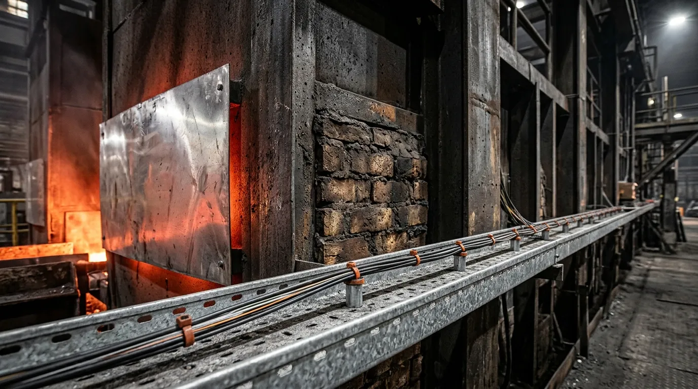
Illustrative image. A heat shield and standoff brackets buy more temperature margin than an upgrade from LSZH to silicone — and they cost less. Measure jacket surface temperature at the hottest hour, not aisle ambient.
Layer 4 — Terminations Are Usually the Weakest Link
You can specify a +200 °C cable and still have a +85 °C link, because the connector at each end was never part of the temperature conversation.
Field-installable connectors are built around an epoxy or adhesive cure and a plastic boot, both of which have their own limits — commonly −40 °C to +85 °C, with a smaller number of industrial families offered above that, so read the assembly's own datasheet rather than inferring its range from the cable. Above the epoxy's glass transition, the ferrule bond creeps, polish geometry drifts, and return loss moves. It fails slowly and it fails at the worst time, because a connector that was fine at commissioning has been heat-cycled ten thousand times by the time anyone measures it again.
The reliable pattern in hot plants is to keep connectors out of the hot zone:
Approach | When it fits | What it costs |
|---|---|---|
Terminate outside the heat | Almost always; run the cable to a junction point in a cool area and connectorize there | Extra cable, one more splice point, a plan for the transition |
Fusion splice through the hot area | Anywhere the link crosses a furnace bay, kiln building or boiler house | Needs a stainless closure rated for the location; no field connector at all |
Factory-terminated assembly | When a connector must sit in the heat and you can state its range | Lead times, fixed lengths, and a range you have to verify rather than assume |
Whatever you choose, include the termination in the acceptance test. A link tested at the panel and not at the far end tells you nothing about the parts actually sitting in the heat.
Prove the Rating: How to Test a High Temperature Fiber Optic Cable
A temperature rating is a claim until someone shows you the test. For optical cable the environmental test methods were consolidated in IEC 60794-1-22:2017, one part of the IEC 60794-1 series whose overall structure is set out in IEC 60794-1-2; that edition is now being replaced part by part, as the note below the table explains. The methods that matter for a hot route:
Method | What it does | Why you care |
|---|---|---|
F1 — Temperature cycling | Cycles the cable between its rated extremes with attenuation monitored throughout | The core evidence that the rating is real, not a material claim |
F9 — Ageing | Soak at elevated temperature with attenuation measured before and after | Catches compounds that pass a cycle but degrade over years |
F12 — Temperature cycling with cable elements fixed at both ends (2017 title: "temperature cycling of cables to be terminated with connectors") | Cycling on cable whose ends are fixed during the test | Tests the assembly you will actually deploy |
F16 — Compound flow (drip) | Measures filler flow at temperature | The gel-migration failure in an upward tube |
F17 — Cable shrinkage / fiber protrusion | Measures how far the fiber moves relative to the tube | The failure that breaks splice closures |
F18 — Mid-span temperature cycling | Cycling on exposed buffer tube | Relevant wherever tube is exposed at a closure or breakout |
IEC has been reissuing these as separate parts of the 60794-1-2xx series — F1 as IEC 60794-1-201, F9 as IEC 60794-1-209, F12 as IEC 60794-1-212, F17 as IEC 60794-1-217 — so quote the current part number in a specification, not just the 2017 method letter.
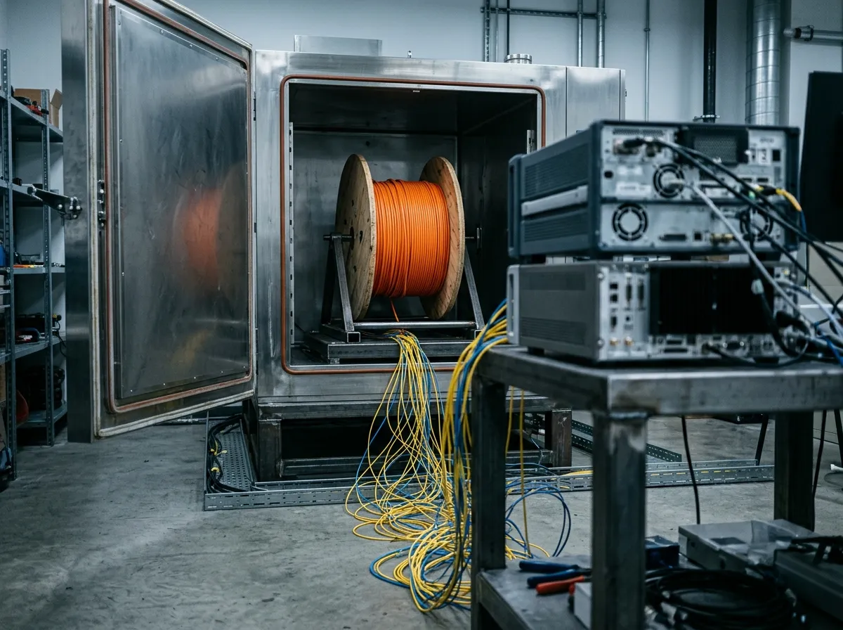
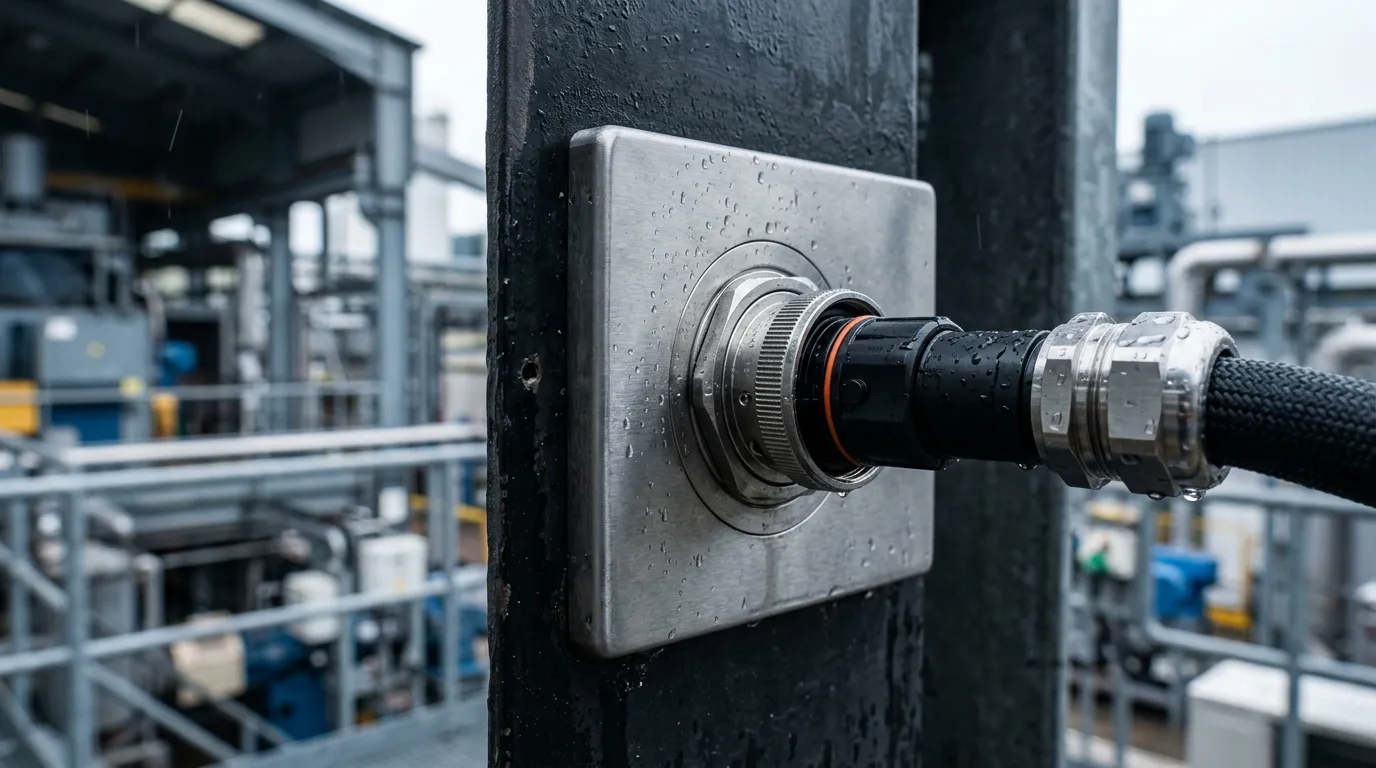
Illustrative image. An F1 temperature cycle is run on a deployed-length sample with the attenuation measured at the test wavelengths throughout — the report, not the brochure, is what tells you the rating is real.
What to ask a supplier for, and what to check in the report:
- The temperature range tested — it must bracket your continuous rating, not your ambient.
- Number of cycles and dwell time — a two-cycle test proves very little; long-form qualification runs many more.
- Wavelengths and the acceptance criterion — the pass criterion is a bounded change in attenuation at the test wavelengths, not continuity. Single-mode specifications often set it at a few hundredths of a dB per kilometer; state the figure in your own spec rather than accepting the supplier's.
- Sample length and deployment — a 100 m sample on a large reel is not the same test as cable coiled at minimum bend radius.
- Who ran it — a third-party report is worth more than a line in a brochure.
Two standards references worth knowing even if you never read them: Telcordia's generic requirements for optical fiber and cable, GR-20-CORE Issue 4, are the document most outside-plant cable is qualified against, and their temperature envelope is the ordinary telecom one — a cable that meets GR-20 and nothing else is not a high-temperature cable. And in North American installations, NEC Article 770.27 is titled Temperature Limitation of Optical Fiber Cables: whatever the cable's listed limits are, using it outside them is a code issue, not just a reliability one.
A Ten-Line Spec You Can Paste Into an RFQ
Most bad high-temperature orders are bad because the requirement was one sentence. Ten lines fix that.
- Continuous operating range: e.g. −40 °C to +200 °C, 24/7, 15-year design life.
- Short-term excursion: e.g. +250 °C for 4 hours, non-recurring.
- Installation and storage range, stated separately.
- Fiber: G.652D, with the coating named (acrylate, high-temperature acrylate or polyimide) and the attenuation spec at 1310/1550 nm.
- Buffer: dry/ePTFE or stainless tube — name the type, not just "loose tube".
- Jacket: material, color and wall thickness, plus the compound's own continuous rating — and state that the assembly rating is the lowest of coating, buffer, jacket and termination.
- Strength member and armor: dielectric or metallic, and why.
- Maximum change in attenuation after F1 temperature cycling, at both wavelengths.
- Test report required: methods, range, cycles, sample length, laboratory.
- Marking: meter marks, cable type, batch and date code for traceability.
If you want the wider construction context — armor, rodent protection, fire ratings, fiber count planning — the industrial fiber optics hub collects the cluster, and the industrial cable guide inside it walks the same decisions for the ordinary −40 °C to +85 °C case.
Where This Cable Actually Goes
- Steel and foundry. Cable trays on the furnace side, cranes with radiant load, and the run from the pulpit to the drives. Expect the jacket surface to run well above aisle ambient — that is the number to measure — and the case is usually solvable with a shield plus a mid-grade jacket rather than an exotic one.
- Cement and lime kilns. Long hot runs, heavy dust, high vibration; the kiln shell radiates for tens of meters.
- Boiler houses and stacks. CEMS analyzer links and burner management data, where the cable often runs inside an insulated enclosure that is hotter than the room.
- Substation trenches and switchgear. Heat from conductors is modest, but the fire and smoke requirements are not — see substation fiber optic cabling.
- Downhole and oil & gas. The one place where +300 °C polyimide and metal tubes are routine; the construction logic is covered in the oil and gas fiber optic cable guide.
- Aerospace, defense and test cells. Short runs, extreme temperatures, weight and crush as the binding constraints — expanded PTFE buffering and high-temperature acrylate are common here precisely because of that combination.
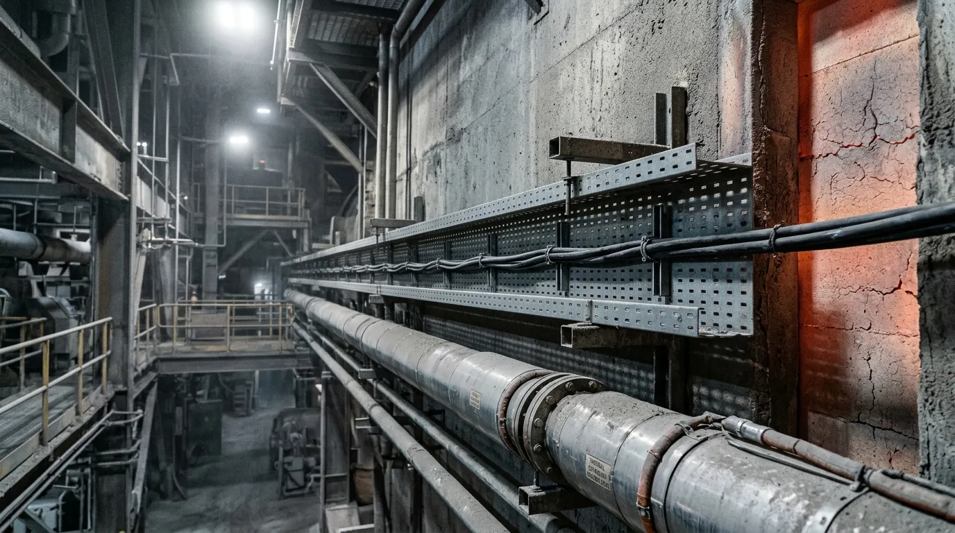
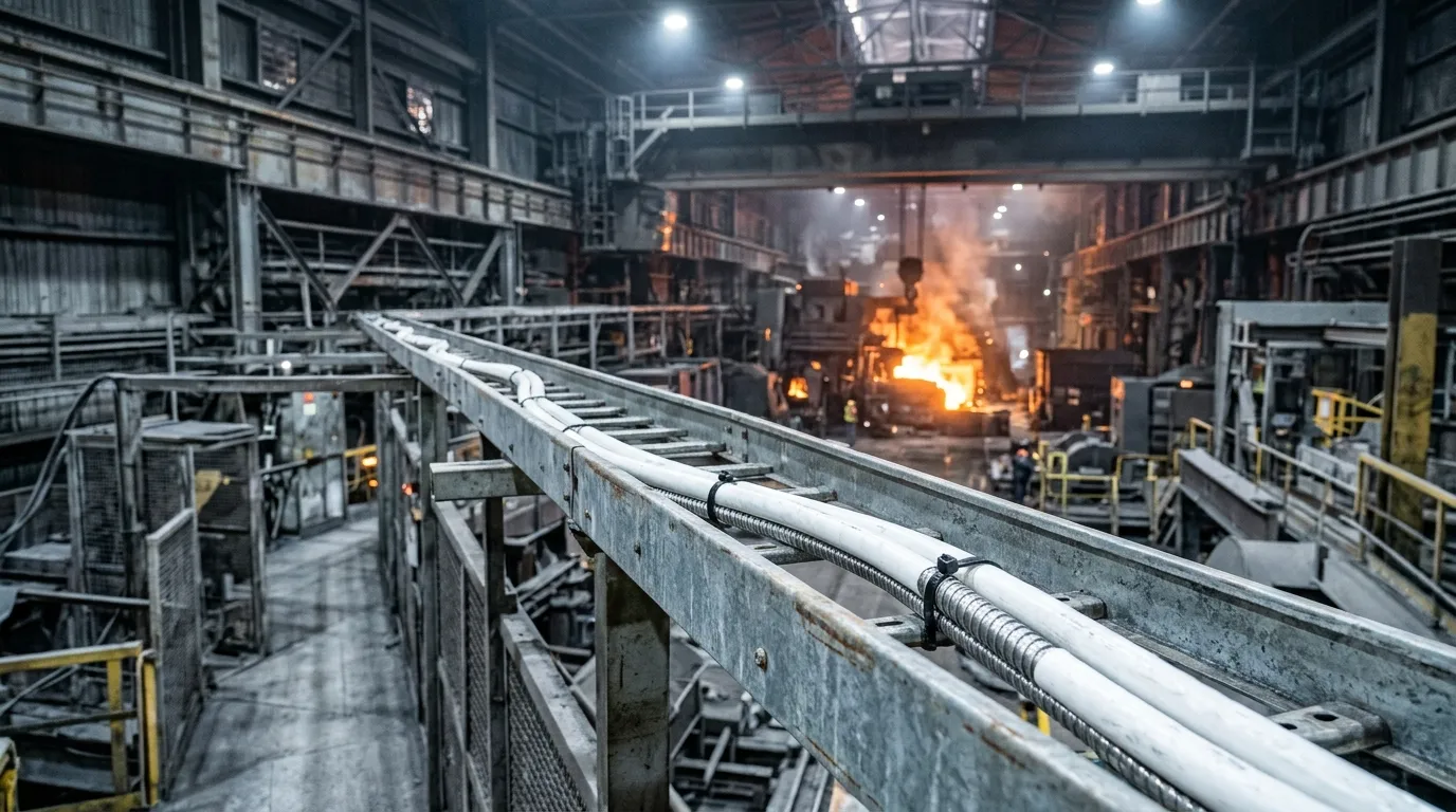
Illustrative image. The kiln building is the classic case: the tray runs beside insulated steam pipe and a refractory wall that stays hot for weeks. The cable's rating has to cover the surface temperature it actually sees, not the air temperature two meters away.
FAQ
What is the maximum temperature for fiber optic cable? There is no single number. Standard cable tops out near +85 °C. Fluoropolymer-jacketed cable reaches +200 °C to +260 °C. Metal-tube cable with polyimide-coated fiber is used above +300 °C. The limit is always the lowest-rated layer in the assembly.
Does high temperature reduce signal quality? Yes, through microbending: differential expansion pushes the fiber sideways and adds loss, often in a way that tracks temperature. The glass itself is not degrading; the packaging around it is.
Can I use standard cable at 100 °C if it is only for a few hours a day? Only if the manufacturer rates it for that duty. Intermittent excursions are a separate rating from continuous service, and the damage — coating oxidation, plasticizer loss, jacket creep — accumulates. A cable rated +85 °C continuous is not rated +100 °C part-time.
Is a PTFE jacket the answer? It is the answer above roughly +200 °C, and it is overkill below +125 °C, where a PUR jacket plus a heat shield is cheaper and easier to install. PTFE is stiff, seam-sensitive, hard to strip, and does nothing for a standard acrylate coating underneath it.
Can I terminate high-temperature cable in the field? Usually you should not. Bring the cable out of the hot zone and splice or terminate there; use factory-terminated assemblies with stated temperature ranges where a connector must sit in the heat.
Does a fiber optic cable measure temperature too? Not this product. Distributed temperature sensing (DTS) and fiber Bragg grating (FBG) systems use fiber as the sensor — a different cable, a different interrogator, and a different specification set. A high temperature transmission cable carries data past the hot zone; it does not measure it.
Next Steps
Write the three temperature numbers down first — continuous, short excursion, installation — then the route's measured surface temperature, then the fiber count. Those five facts are enough to fix the coating, the jacket, the construction and the termination approach, and they are the same five facts a cable factory needs to quote you accurately.
TTI Fiber builds outdoor cable in-house, from fiber coloring to jacketing, across ADSS, central and stranded loose tube, armored and air-blown constructions from 2 to 288 cores on ITU-T G.652D fiber — the standard outdoor range, which most of those constructions list at −40 °C to +70 °C. If your measured surface temperature lands above that, tell us, and we will say whether the answer is a construction we build or a fluoropolymer or metal-tube cable you need from a specialist, rather than quoting you the nearest thing on the shelf. Send the temperature profile and the route to our team and we will answer on that basis.