Oil and Gas Fiber Optic Cable Guide
Ask five cable suppliers for an oil and gas fiber optic cable and you may get five different quotes — loose-tube here, tight-buffer there, steel tape armor, no armor, LSZH jacket or PE. None of them is necessarily wrong, and that is exactly the problem: in a refinery or on an offshore platform, the cable that is merely acceptable in one zone can be a fire-load or maintenance liability in the next. The environment decides the construction, and the standards decide what "good enough" means. This guide walks through both, segment by segment, so you can write a spec instead of hoping a datasheet covers you. It sits inside our wider library on fiber for harsh industrial environments, alongside practical buying guidance for the field.
What an Oil and Gas Fiber Optic Cable Has to Survive
An oil and gas fiber optic cable is not one product but a family of constructions, each tuned to a different mix of stresses. Before comparing cables, separate the stresses, because they rarely arrive together:
Environment | Dominant stresses | Typical routing |
|---|---|---|
Onshore plant / refinery | Process heat, chemical vapor, fire load, mechanical impact | Cable tray, conduit, rack above grade |
Offshore platform topside | Salt spray, UV, vibration, classified (hazardous) zones | Steel tray on deck and pipe racks |
Subsea / riser | Hydrostatic pressure, seawater, flexing, tension | Umbilical, riser, J-tube, subsea control |
Downhole | Heat (150°C and up), hydrogen, pressure, crude exposure | Tubing-conveyed, clamped to production string |
Pipeline right-of-way | Burial load, rodents, water, ground movement, lightning | Direct buried or duct, aerial at crossings |
Temperature, chemicals and pressure get most of the attention, and they matter. But in practice three quieter killers cause more field failures: water ingress, hydrogen darkening in hot wells, and mechanical damage during installation. Water blocking and armor are not optional extras on a long outdoor or buried run — they are the difference between a 25-year asset and a cable you dig up twice.
Where Fiber Earns Its Keep in Oil and Gas Operations
Fiber appears in oil and gas in two roles: a network backbone and a sensor. The two are frequently the same fiber, which is why the cable spec matters to both the instrumentation and the telecoms engineer.
The backbone role is the familiar one: plant-wide SCADA, process control and safety-system networks, wellhead-to-platform links, and platform-to-shore trunks where distances run to tens of kilometers. In these runs the cable is competing with copper on distance, immunity and weight.
The sensing role is what makes oil and gas special. Distributed acoustic and temperature sensing (DAS/DTS) turns a standard single-mode fiber into a continuous line of sensors that can locate a pipeline leak, track flow, or profile temperature along an entire well. The U.S. DOE's National Energy Technology Laboratory describes fiber-optic sensing as a tool for shale fracture monitoring, mapping fracture growth to optimize production from unconventional reservoirs. When a fiber doubles as a sensor, its attenuation stability over years matters far more than peak bandwidth.
The role people overlook is the plant utility network: CCTV for flare and perimeter monitoring, PAGA (public address) systems, and the low-voltage data links that modern terminals run everything on. Those runs are short and undemanding — until the cable jacket fails a fire test in a plant audit. Fire performance is a procurement requirement, not a performance option, in every facility with a permit to operate.
Fiber vs. Copper in the Plant: What the Switch Buys
The engineering case for fiber in oil and gas is not that light is "modern." It is that three properties of the medium solve plant problems directly:
- Immunity. Fiber carries no electrical signal, so electromagnetic interference from switchgear, VFDs and induction motors — the same interference that haunts fiber optic cabling in high-EMI substations — simply does not couple into it. Ground loops between buildings disappear when the link is dielectric.
- Distance and weight. A single-mode fiber spans wellhead-to-control-room distances that copper cannot reach without repeaters or converters, and a fiber cable weighs a fraction of an equivalent copper bundle — a real number on offshore topsides where every kilogram is budgeted.
- Explosion-risk behavior. At the glass itself there is no spark source and no ignition energy to manage, which is why fiber is attractive in classified areas. Draw the boundary honestly, though: the complete cable assembly is not automatically "intrinsically safe." Metallic armor, screens and strength members conduct, and every entry into a classified enclosure still needs a certified gland and correct bonding. The reference for how electrical installations — including cable systems — are designed, selected and installed in explosive atmospheres is IEC 60079-14, and site practices should be checked against it and against the facility's own area-classification drawings.
None of this means copper disappears. Instrument loops, power and legacy fieldbus stay copper. Fiber wins the long, the noisy, and the safety-critical data paths.
Choosing Cable Construction for Each Environment
Construction is where oil and gas cable buying actually happens. Four building blocks combine to fit an environment: the buffer system (how fibers are protected), the armor (how the cable survives crushing and rodents), the jacket (fire, chemical and water performance), and water blocking (how the cable dies if the sheath is breached). Our industrial fiber optic cable guide covers these building blocks in depth; here is how they map to oil and gas environments.
Onshore plants and refineries
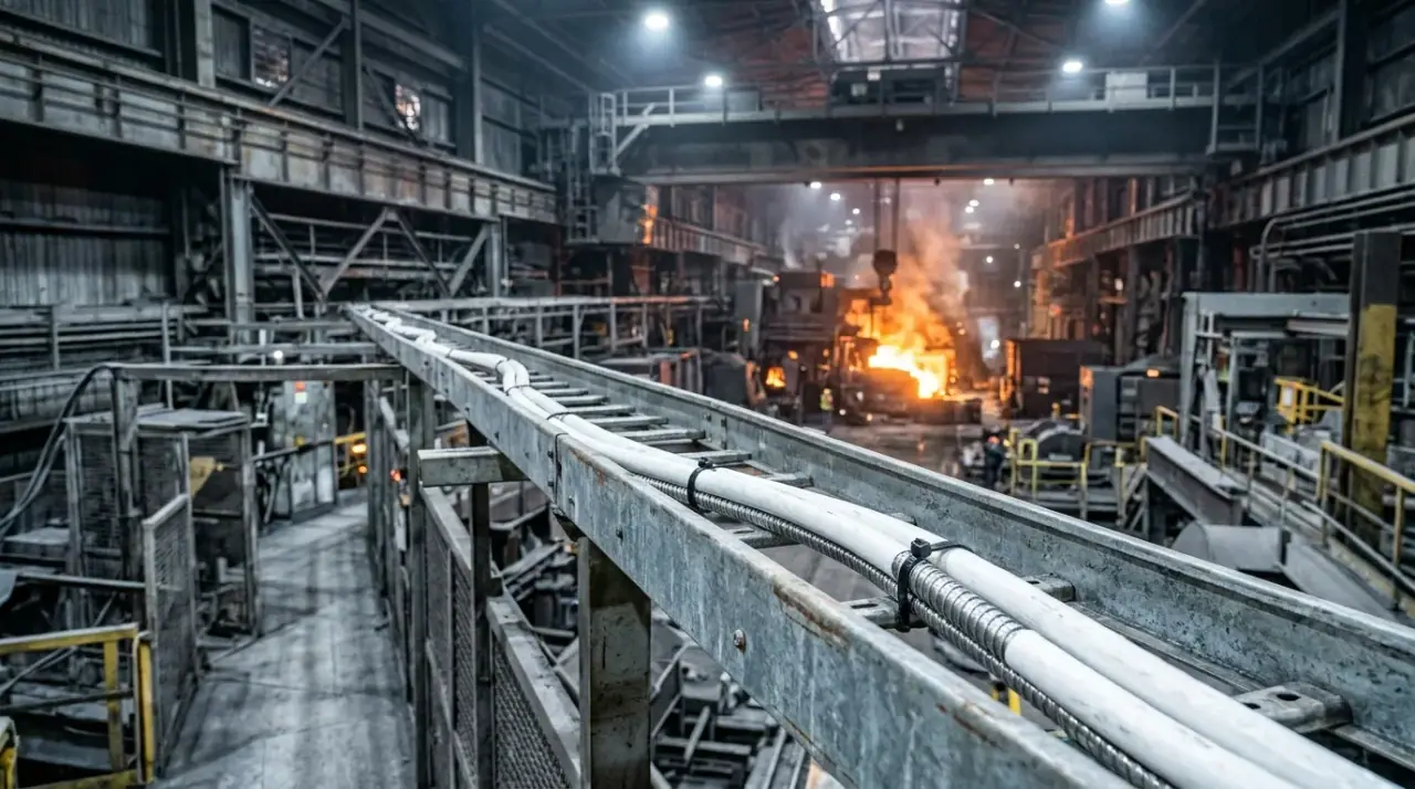
Inside control buildings and marshalling cabinets, tight-buffered cable terminates directly onto connectors with no splice tray — fast, clean, and standard for the short, protected hops where most plant fiber actually lives. The moment the cable leaves the building or runs in open trays, switch the priorities: flame-retardant, low-smoke, zero-halogen (LSZH) jacket for fire load, and a flame-spread rating for bunched runs.
This is the point where a flame retardant fiber optic cable stops being a nice-to-have. Refinery cable trays are densely packed, vertical risers concentrate the fire load, and evacuation time depends on smoke. The IEC test that bunched optical cables must pass for vertical flame spread is IEC 60332-3-22 (Category A), part of the 60332 series that explicitly covers optical fiber cables under fire conditions. If a supplier cannot show the 60332 report for the exact construction you are buying, treat the fire rating as unproven.
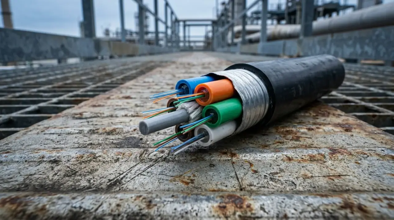
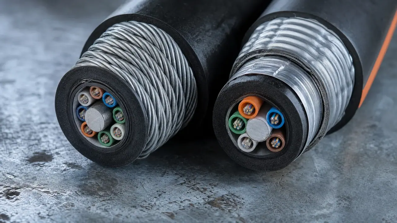
Cutaway of a typical plant cable: LSZH jacket over steel-tape armor over loose tubes — the construction behind most refinery tray runs.
Offshore topsides
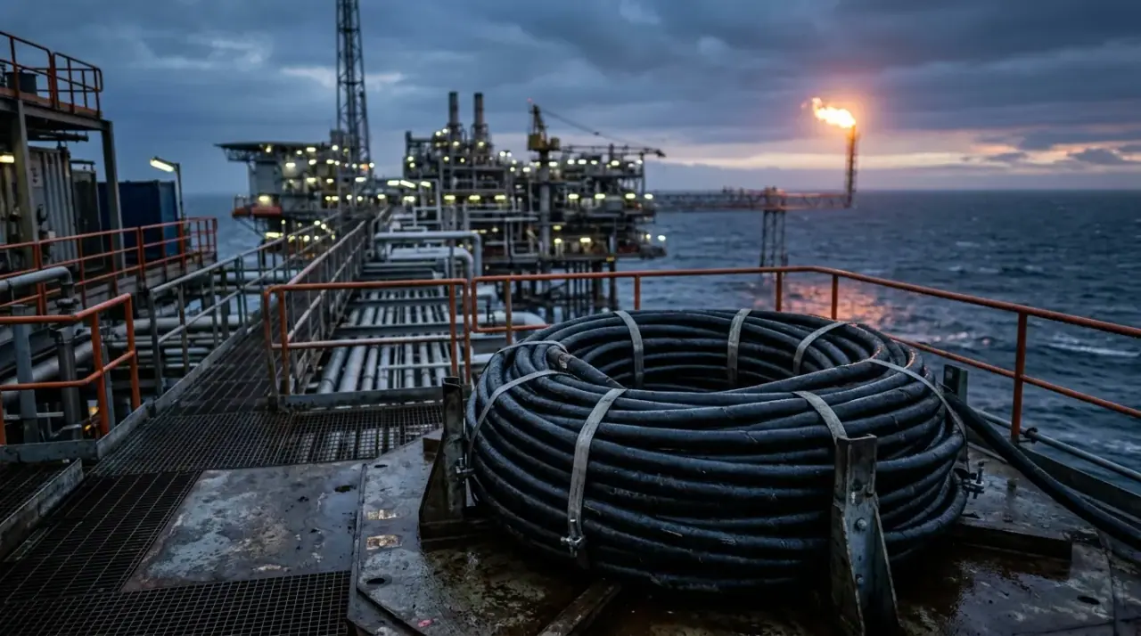
Add salt, UV and motion to the plant recipe, and the jacket and armor choices tighten. Offshore platforms are compact: cable trays crowd process areas, and much of the platform is inside classified zones, so area classification drives the cable and its terminations. In U.S. waters the requirement is regulatory: 30 CFR §250.114 requires OCS platforms to classify locations per API RP 500 or RP 505 and to install electrical systems per API RP 14F or 14FZ. Read that as your cable's armor, glands and bonding needing to fit a documented classification scheme, not as "fiber needs no protection" — the cable is part of an installation, and the installation has a class.
Subsea and riser systems
Subsea is a different engineering world. The offshore fiber optic cable that matters here is rarely a standalone cable at all: it ships inside a steel-tube or polymer-tube umbilical alongside power and hydraulic lines, engineered for hydrostatic pressure, fatigue and installation tension. Pressure rating on these assemblies is a design output, not a datasheet headline: state the hydrostatic head at installation depth plus the installation and operating loads, and ask for the pressure-cycle test report on the exact construction. Design, materials, manufacture and testing of these umbilicals — including ones carrying optical fibers — were governed by ISO 13628-5:2009 in the petroleum industry's subsea production-systems family; ISO withdrew that edition on 8 December 2025, and the corresponding active specification is now API Spec 17E (5th edition, 2017), whose fourth edition was the identical adoption of ISO 13628-5:2009. A project specification that still names ISO 13628-5 should be updated to the current edition before you quote against it. If your project involves a subsea fiber optic cable, the specification almost always lives at the system level (umbilical or riser), not in a generic cable datasheet.
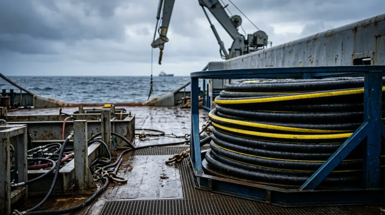
A subsea umbilical — the steel-tube armored assembly in which subsea optical fibers travel.
Downhole
Downhole fiber operates where nothing else electronic survives for long: sustained heat, hydrogen-rich well fluids, and pressures that crush commodity cables. Two properties dominate the spec: the fiber's own tolerance for hydrogen (which causes attenuation growth, "hydrogen darkening," in hot wells — the reason downhole fibers are often hermetically carbon-coated) and the cable's ability to survive installation and production loads in a metal tube. Temperature capability is application-specific: shallow and injection wells are far gentler than deep producing wells, so specify against the actual well's temperature profile rather than a generic "high-temperature" label. There is no universal downhole cable; there is a cable for your well's completion.
Pipeline right-of-way and buried runs
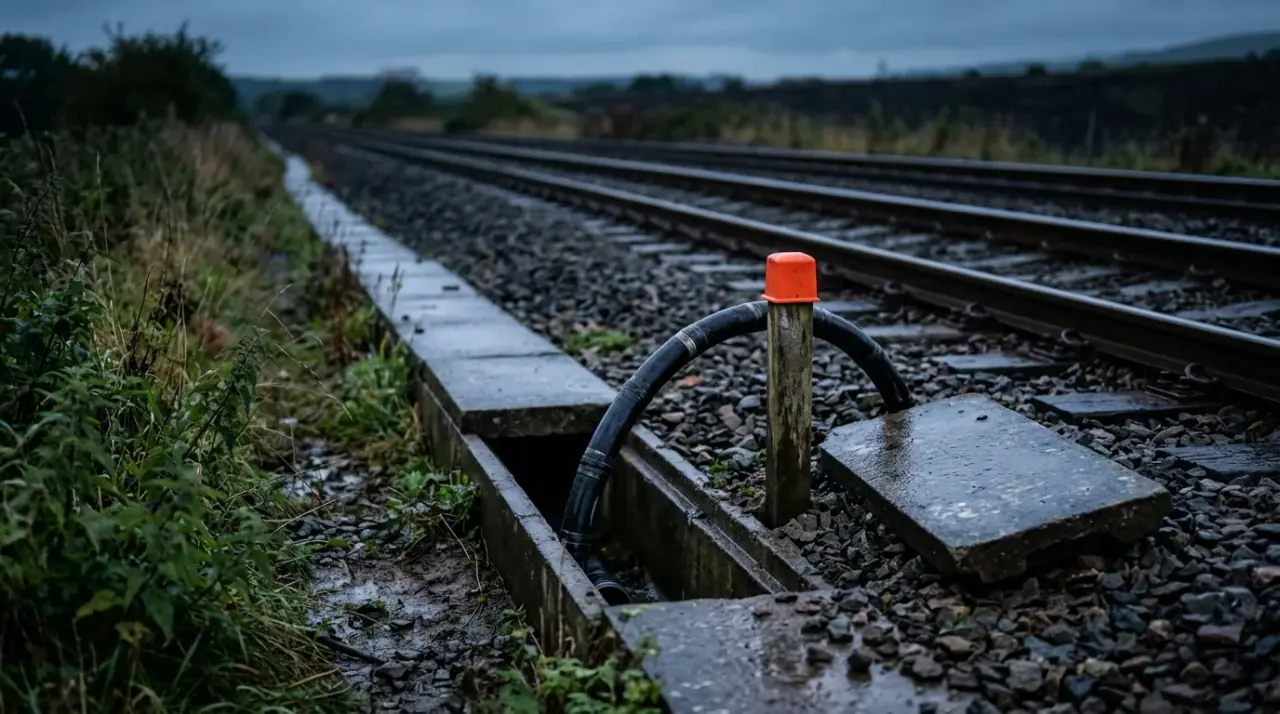
For buried or aerial runs along pipelines, the cable is an outdoor plant asset first. That means outdoor-rated construction — steel tape or wire armor against rodents and backfill, fully water-blocked core and sheath, and a jacket that survives UV and ground chemicals. Our rundown of outdoor armored fiber optic cable types covers the armor vocabulary (the GYTS/GYTA/SWA family and when each applies); for oil and gas ROWs the selection usually lands on the heavy end of that range, with duct or direct-burial protection chosen on the same criteria as any industrial pipeline telecom route. A buried pipeline run is also a monitoring asset: the same fiber can carry distributed acoustic sensing that flags leaks and third-party excavation along the right-of-way, so decide whether you want that capability at design time rather than retrofitting it later. Where a ROW runs near other severe environments, the same logic that drives fiber optic cable for mining applies: if the ground or the process can damage it, armor it once.
Single-Mode or Multimode for the Field
Almost every oil and gas application resolves to single-mode, for three reasons. Distances exceed multimode's comfortable reach; sensing systems (DAS/DTS) require single-mode fiber; and a field network expected to carry new line rates for two decades should not be capped by an older multimode choice. The global reference for standard single-mode fiber is ITU-T G.652 (current edition 08/24), and G.652.D-class fiber is the default for outdoor, subsea and downhole links. If you are comparing single-mode vs multimode for a control-room LAN of a few hundred meters, multimode remains legitimate and cheaper to terminate — but it stays inside the building.
Oil and Gas Fiber Optic Cable Standards: What Actually Applies
Standards are where most published oil and gas fiber articles go vague, so here is the mapping in one place. For cable construction itself, the governing family is IEC 60794 — its outdoor-cable parts set the functional, mechanical, environmental and optical requirements for the external cables an oil and gas plant installs. The table below is a starting map, not legal advice: your facility's class, the flag state's regulations, and the project spec all override a generic reading.
Standard / code | What it governs | Where you meet it |
|---|---|---|
IEC 60794 series | Optical fiber cable construction, mechanical and optical requirements | Cable datasheets and type tests |
IEC 60332-3 | Flame spread of bunched cables, incl. optical | Fire-rated tray runs in plants |
IEC 60079-14 | Electrical installation in explosive atmospheres | Classified-area cable runs and terminations |
API RP 500 / 505 | Area classification (Division / Zone) at petroleum facilities | Platform and plant classification drawings |
API RP 14F / 14FZ | Electrical systems on offshore platforms (Div. / Zone) | Offshore topside cable installation |
API Spec 17E (formerly ISO 13628-5) | Subsea umbilicals (incl. optical fibers) | Umbilical procurement |
ITU-T G.652 | Standard single-mode fiber characteristics | Fiber specification for SM links |
Two habits keep a spec honest. First, cite the edition — "IEC 60794" means little; "IEC 60794-3:2022" means something a buyer can check. Second, ask for the test report, not the compliance claim. A supplier's "LSZH" or "flame retardant" label is only as good as the IEC 60332 / IEC 60754 report behind it.
Selecting and Specifying: A Field Checklist
When you sit down to write the requisition, work through the environment in this order:
- Define the route and the zone. Draw the cable path; note every classified area, riser, outdoor transition and burial segment on it.
- Fix the fiber type. Single-mode G.652.D for anything outside a control building; multimode only for short indoor hops.
- Set the buffer system. Tight-buffer where it terminates directly indoors; loose-tube where temperature swings and water are risks.
- Add armor by threat. No armor for protected indoor runs; steel tape for tray and duct; steel wire for burial, rodents or high crush.
- Specify the jacket. LSZH with a bunched flame-spread rating inside and around buildings; outdoor PE or LSZH-outdoor for exposed plant runs.
- Require water blocking on any cable that leaves a conditioned space.
- Check the environmentals — operating temperature range against the actual route, not the brochure maximum.
- Collect the documents: datasheet, type-test reports for the exact construction, flame/spread test report, and lot-level test data (attenuation per fiber, length accuracy).
When you send that requisition to a manufacturer, the conversation changes. Instead of "what fiber optic cable for oil and gas do you sell," you can ask: does this construction pass IEC 60332-3-22 with the bunched volume we specified, what is the crush rating of the armor layer, is the core fully water-blocked, and can you ship the type-test reports with the lot? TTI Fiber, an ISO 9001:2015-certified manufacturer of armored, LSZH and outdoor fiber optic cables, builds to these IEC construction standards and answers those questions with test data rather than adjectives.
Installation and Testing That Keeps It Reliable
Most oil and gas fiber failures are installed, not manufactured. Three practices prevent the classics:
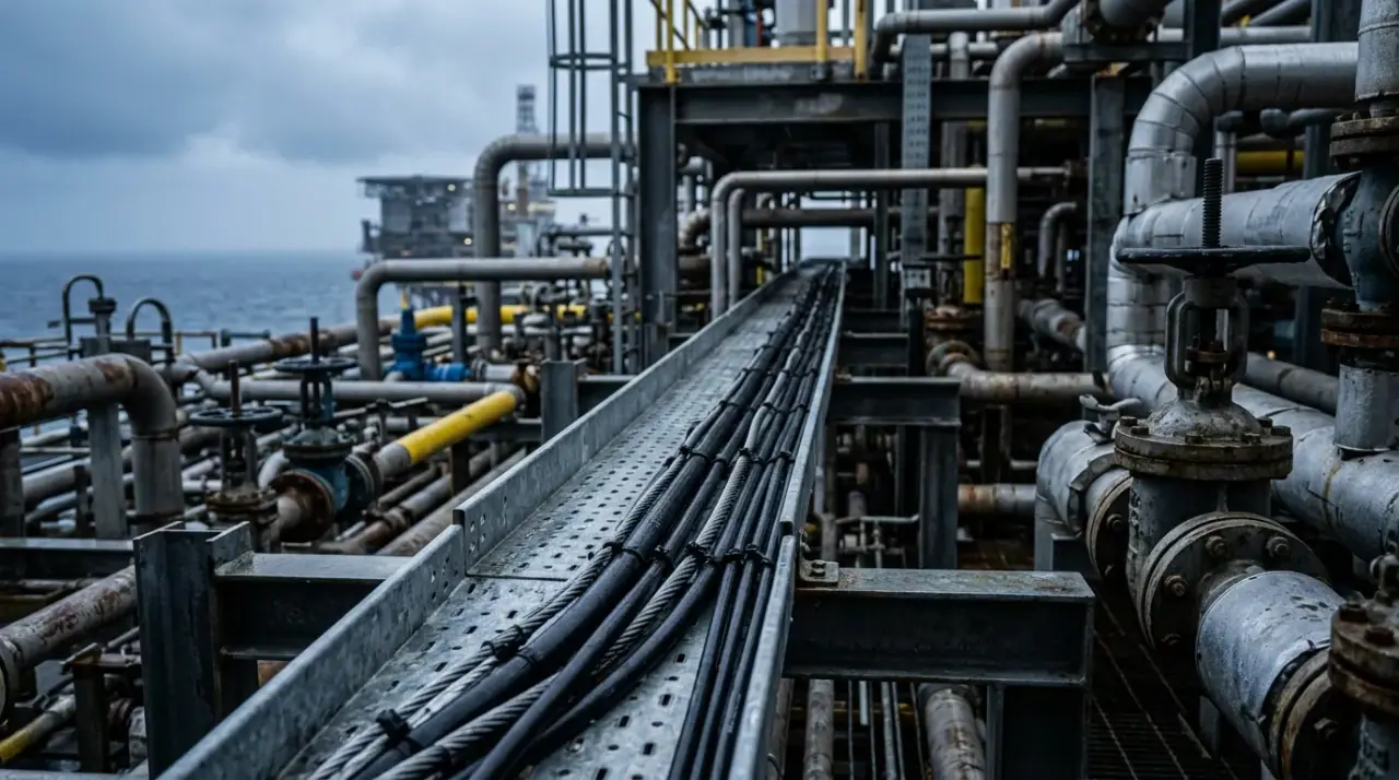
Armored cables on a topside tray run — routing and segregation decided at design time, not on site.
- Respect the bend and the pull. The minimum bend radius during installation (typically ten times the cable diameter under tension for armored cables) protects the fiber from micro-bending that no test afterward can fully reverse. Use a pulling grip on the strength members — never the jacket — and keep the pull under the cable's rated tension.
- Ground the armor, seal the entries. Metallic armor and screens must be bonded and grounded at the correct end per the installation standard, and every gland entering a classified enclosure must suit the zone. This is the part that turns a "fiber is safe" assumption into a documented installation.
- Baseline it with an OTDR. After installation, an OTDR trace and insertion-loss measurements per span give you the signature that future troubleshooting compares against. Connector contamination is the most common field fault in dirty environments; inspect and clean every connection before the final test, and record the results with the as-built drawings.
None of this requires exotic equipment — it requires that the cable spec, the installation method and the testing plan be written down before the spool leaves the warehouse.
Oil and Gas Fiber Optic Cable FAQ
Do I need a special hazardous area fiber optic cable? There is no separate "hazardous area" product category to buy; what matters is the installation. Fiber's dielectric nature is one reason it is attractive in classified areas, but the cable assembly, its metallic members, glands and bonding still have to comply with the area classification and the installation standard (IEC 60079-14, or API RP 14F/14FZ offshore), so treat a hazardous area fiber optic cable as an installation requirement, not a product feature.
Single-mode or multimode for an oil and gas plant? Single-mode for anything beyond a few hundred meters and for any sensing application; multimode only for short indoor LAN hops where termination cost matters.
Why do downhole fibers go dark over time? Hydrogen from well fluids diffuses into the glass at high temperature and raises attenuation — "hydrogen darkening." Downhole cables counter it with hermetically carbon-coated fiber and metal-tube protection.
Does armored fiber optic cable need grounding? Steel tape, wire armor and metallic screens should be bonded and grounded per the installation standard to avoid induced voltages and to give faults a defined path. Dielectric (armorless) cables skip this — which is why they are chosen where lightning or ground loops are the bigger threat.
The short version of all of the above: define the route, the zone and the fire class first, and the cable construction follows. Send TTI Fiber's engineering team your environment — classified areas, temperature range, mechanical loading, and whether the run is indoor, outdoor, buried or subsea — and they will recommend a construction built to the relevant IEC and ISO standards, with the test reports to back it.