How to Specify Railway Trackside Fiber
The cable that fails on a railway is rarely the cable that looked wrong on paper. It is the one routed in the wrong place, pulled around a bend it should never have seen, or left in a trough that filled with water and fines the first winter. Railway trackside fiber lives in a corridor where the ground moves and a high-voltage traction system drives current through a defined return network, including the running rails and, where provided, designated return conductors.
This is a specification walkthrough, not an introduction to optical fiber. It works through six decisions — zone the route, name the threats, fix the construction, match the standards, plan the installation, test what you built — and ends with a checklist you can hand to a supplier, plus the one conflict most trackside specs miss.
What "Trackside" Covers — and What It Doesn't
A trackside route is not one environment. It is at least four, and the cable's duty changes between them.
- Open line. Concrete ground-level troughing in 1 m sections with detachable lids, buried duct, or cable direct-buried along the cess. Long, exposed, wet.
- Tunnel and covered way. No trough lids, no controllable drainage, restricted access, and a fire and evacuation problem that changes the material question.
- Station, platform and junction areas. Short drops, many joints, dense cable, and a maintenance population that is not a cable crew.
- Level crossings and equipment areas. Buried approaches, frequent third-party work, and a high chance of accidental damage.
The traffic is not office traffic: interlockings and train control systems, the operator's IP backbone, station and crossing CCTV, and the links from the control center to the equipment rooms share one corridor, and are all expected to work with a train somewhere on the route.
"Trackside" here means the fixed fiber infrastructure inside the railway boundary, plus its links into signaling and telecoms equipment rooms. It is not wayside or train-to-ground radio — the wireless layer, whose limits are exactly why trackside fiber demand keeps growing — and it is not rolling-stock cabling, which follows a vehicle standard. Distributed sensing can share the cable, with one caveat covered below, but it is selected differently.
The Enemies on a Trackside Route
Every line in a trackside specification should trace back to a physical threat. These are worth tracing.On an electrified line, traction return current normally follows the running rails and any designated return conductors. Metallic armor, screens, or other continuous conductive elements near the traction system can experience induced voltage and current, and may carry fault or return current if they are connected into the railway bonding network. Their routing, bonding, earthing, separation, and surge protection therefore require a project-specific railway electrical design; they must not be treated as an automatic return path. The fiber is immune to interference because the signal is light. The armor is not immune to being a conductor. Bonding, earthing and separation are route decisions, not accessories.
Lightning and switching transients. Open-country routes are the most exposed part of the network, and a surge arriving on a metallic element travels to whatever the cable connects to at each end.
Water in the trough. Ground-level troughing beside a ballasted formation collects rain and fines, and freeze-thaw works on anything that will not drain. Water inside a jacketed cable is a design failure; water in a trough is normal operating conditions.
Ballast, settlement and track machinery. The formation settles, lids move under footing and tamping, and on-track plant works in a space measured in centimeters.
Rodents. A trackside route is a habitat with a continuous food supply and a long, warm, hollow structure to gnaw on. This is a monthly event, not an edge case.
Cable theft. The one threat where fiber has a structural advantage: copper signaling and telecom cable is stolen for scrap value, a documented problem for infrastructure owners, while bare fiber has little intrinsic scrap value compared with copper. That is a business-case argument, not only a technical one.
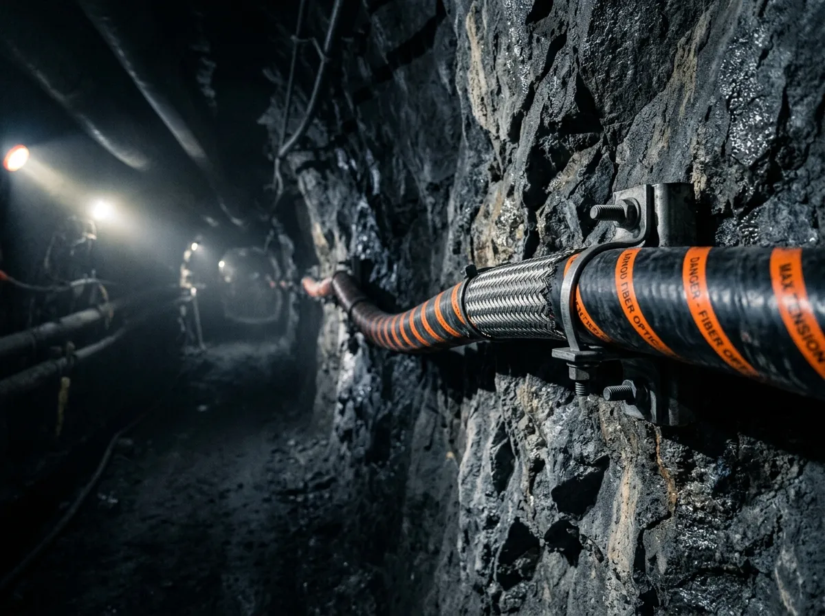
Tunnel fire and evacuation. Inside a tunnel, cable is not only infrastructure. Whatever it is made of is part of what burns, what smokes, and what people breathe while they walk out.
Access and possession time. Every item above has to be installed and maintained in a window of a few hours between trains.
Notice what is not on that list: bandwidth. The threats are mechanical, environmental, chemical and thermal, and a cable chosen for a data center optimizes for none of them. For harsh routes the sequence is construction first, glass second — the same order used across industrial fiber optics for harsh, remote environments generally.
Cable Construction That Answers Each Threat
Buffer construction. On long outside routes the fiber sits inside a loose tube, decoupled from the cable's strain. Tight-buffered construction suits short, terminated runs.
Water blocking. Water travels along a cable from any breach, so the block must be longitudinal. Gel-filled tubes and dry water-swellable tapes both work; the choice depends on whether splicing crews on the route will tolerate gel.
Strength members. The fiber must never carry the pulling load. A central member plus aramid or glass yarns take the tension, and the tension rating is a number you specify.
Jacket. Polyethylene is the normal outdoor choice for moisture and ultraviolet resistance. Halogen-free, low-smoke compounds may be required in tunnels, stations and other confined spaces, depending on the applicable infrastructure, fire and project requirements.
Armor. Steel tape or steel wire armor adds crush and rodent resistance, and is why some trackside cables can be laid on the formation shoulder with no trough at all. It introduces a metallic element whose bonding, earthing, isolation, and surge-protection treatment must be defined by the railway's approved electrical design, and it changes the answer on sensing. All-dielectric construction avoids the bonding problem and gives up the protection.
Mechanical and thermal ratings. Publicly available datasheets for cables marketed to the UK trackside cable standard family (NR/PS/TEL/00014) list values such as a minimum bend radius of 12× the overall diameter, an operating range around −20 °C to +60 °C, crush resistance near 300 N/cm, and laying tension in the low kilonewton range. Treat these as illustrative product values, not universal railway requirements. Confirm every number against the current controlled issue of the standard and the infrastructure manager's project specification.
Two points matter more than the numbers themselves. The installation range is always narrower than the operating range, because the jacket is the constraint while the cable is pulled. And a bend radius stated as a multiple of diameter means the same cable gets stiffer as its diameter grows.
Fiber type and count. Single-mode is the default, and the ordinary ITU-T G.652 specification is what most rail signaling fiber and railway telecom cable on these routes is built to. Budget the joints as well as the endpoints: every joint bay consumes fibers for breakouts.
Cable construction practice for these routes is summarized in the FOA reference on fiber optic cables.
For the armor options themselves, see our guide to outdoor armored fiber optic cable types.
Threat | Construction answer | What to ask the supplier |
|---|---|---|
Traction current, EMI | Dielectric construction, or a defined bonding and earthing scheme | Is any element metallic, and what is the bonding provision? |
Lightning and surges | Metallic armor requires a defined bonding, earthing, isolation and surge-control design; surge-protection devices shall be installed where required by the approved railway electrical design. | What surge path does the design assume? |
Water ingress | Longitudinal block: gel tubes or swellable tape | Which cable test method is the water block tested to? |
Crush and settlement | Steel tape or steel wire armor with a stated crush rating | Crush rating in N/cm, and how it was measured |
Rodents | Steel armor; hardened jacket where armor is impossible | Evidence from a rodent test, or a protected route |
UV and weather | Black polyethylene outer jacket | UV stabilization of the exact jacket compound |
Tunnel and confined space | Halogen-free, low-smoke jacket in those sections | Which fire standard applies to your route, in writing |
Installation mechanics | Bend radius, pulling tension, installation temperature | Installation range stated separately from operating range |
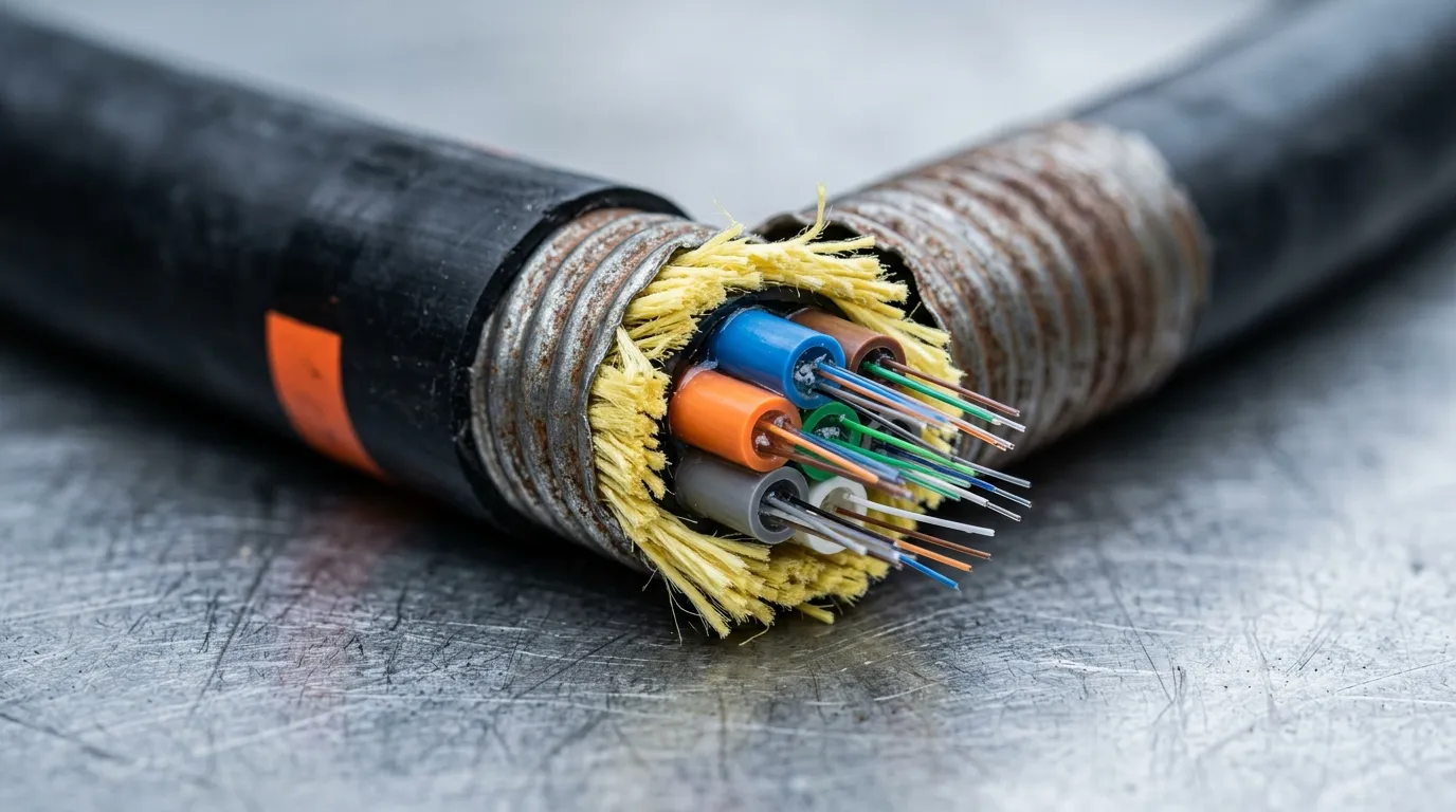
Illustrative construction, not a manufacturer's drawing. Armor answers crush and rodents, and creates the bonding, earthing and sensing problems — three of the rows above trace back to it.
Railway Standards: What Each One Actually Governs
Trackside cable is not governed by one standard, and the one quoted most often in supplier marketing is frequently the wrong one.
EN 50121-4 sets electromagnetic-emission and immunity requirements for signaling and telecommunications apparatus installed in the railway environment. Its 3 m and 10 m zones, together with the applicable connection conditions, are used for apparatus EMC assessment. The standard does not qualify the fiber cable itself; cable metallic elements, equipment interfaces, bonding, earthing and route installation require separate project requirements.
ITU-T G.652 defines the single-mode fiber itself. Some sensing duties use a low-water-peak profile instead, which is why that distinction exists.
IEC 60794 is the optical-fiber-cable standards family. Its parts define applicable cable specifications and test methods for mechanical and environmental performance; the required rating and acceptance limit still come from the applicable sectional or product specification and project documents. When a datasheet quotes a crush, tensile, or temperature value, ask for the exact IEC 60794 method and the requirement against which the value was assessed.
NR/PS/TEL/00014 is the UK trackside cable standard family — Network Rail's specification for trackside optical cable. It is national rather than international. Its parameter set — bend radius, temperature, crush, tensile and attenuation — may provide a useful engineering reference, but it is not a generic template or a substitute for the applicable national railway standard and infrastructure manager's project specification.
EN 45545-2 is the fire standard for railway vehicles: fire behavior requirements for materials and components, and the most commonly misapplied standard in this space. A cable fixed beside the track is not a vehicle component, and citing EN 45545-2 for it demonstrates nothing. If your scope includes rolling stock, it applies, and the published scope is explicit about that. For fixed infrastructure, ask the infrastructure manager which national fire requirement governs the route, and get it in writing.
TIA-598 is the fiber color code. It looks trivial until you are identifying tube 7, fiber 19 inside a closure in the rain.
What to ask for as evidence: accredited-laboratory test reports, operating and installation ranges declared separately, and a plain statement of which standards the cable is and is not qualified to. "Meets railway standards" is not a specification. Power networks hit the same problem, where substation fiber optic cabling faces comparable EMC and routing constraints under a different standard set.
Standard | What it actually governs | What to ask for |
|---|---|---|
EN 50121-4 | EMC environment for signaling and telecoms apparatus, by zone from track | EMC evidence for the apparatus, not the cable |
ITU-T G.652 | The single-mode fiber itself | Which fiber spec, and is a low-water-peak profile needed? |
IEC 60794 | Cable test methods and sectional specs | The test method behind every mechanical rating |
NR/PS/TEL/00014 | UK trackside cable parameters | A datasheet mapped to it, item by item |
EN 45545-2 | Fire behavior of materials in railway vehicles | Whether your scope is actually a vehicle scope |
TIA-598 | Fiber color identification | That cable, pigtails and closure agree on the code |
Routing: Where the Cable Actually Goes
The route is the specification. Five options cover most trackside work, each with its own failure mode.
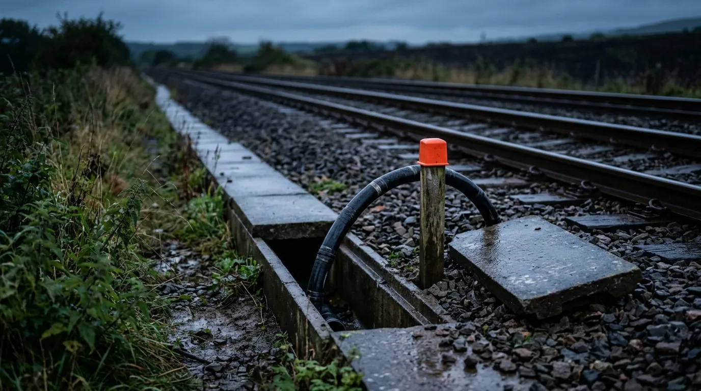
Concrete ground-level troughing. The traditional route: 1 m sections with detachable lids, cable laid in and lids replaced. The cable stays accessible and inspectable for the life of the route — at the cost of needing track access to install it and to lift lids later, plus displaced lids, ballast ingress, and a trough that collects water and fines.
Direct burial. Ploughing or trenching in the cess with screened backfill and a marker tape, at whatever depth the infrastructure manager's standard sets. Cheaper per meter, but you cannot inspect it, and every future excavation near the railway becomes a risk to it.
Buried duct with air-blown fiber. Install empty duct, then blow fiber bundles through it with compressed air. This separates civil work from cable work: the expensive, access-hungry step happens once, and capacity is added later by blowing fiber into spare ducts. How far infrastructure managers have actually adopted it varies, and how a duct route behaves as the network around it expands is a legitimate design question — so confirm your infrastructure manager's position before designing around it. Where a duct route is agreed, air-blown micro cable is the cable end of that decision.
Route-free heavy armor. Where there is neither trough nor duct, a heavily armored cable may be used only where the infrastructure manager's approved route design permits placement on the formation shoulder and specifies the required clearances, anchoring, protection and maintenance access. The classic network example carried 24 single-mode fibers in two stainless steel tubes wound helically around a solid aluminum former, under a polyethylene inner sheath, thick steel wire armor and a fire-retardant oversheath, scratch-buried and secured roughly every 40 m. That cable is no longer a current product, but the pattern is worth understanding: armor heavy enough to replace a civil route. Rail Engineer's account of trackside cable infrastructure is the best public description of these routes and of the theft economics that shape them.
Aerial spans and elevated troughing. In cuttings and across difficult ground, taking the cable off the formation keeps it out of the water and out of the ballast, trading those problems for sag, wind loading and long-term movement.
Two procedural rules apply to all five. Drum length drives joint count: trough routes have traditionally been installed in sections of up to about 2 km, with selected fibers broken out at each joint, and every breakout is a place where the cable is opened. And the possession window governs the plan — off-loading, troughing and pulling generally need the track, so the design work that pays off keeps installation off-track and in-possession joints to a minimum.
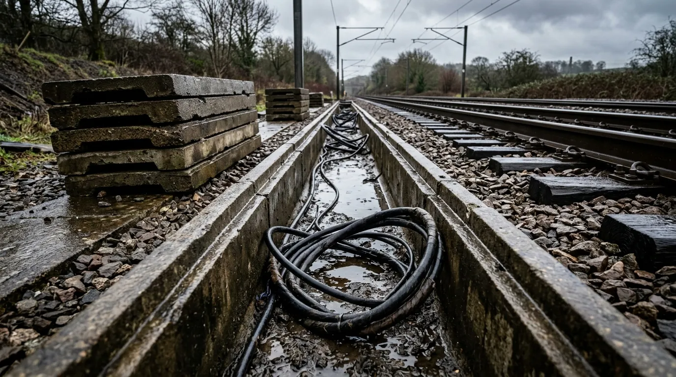
Lids stacked to one side, channel full of water: the trough route is inspectable, and needs a possession for every one of those lids.
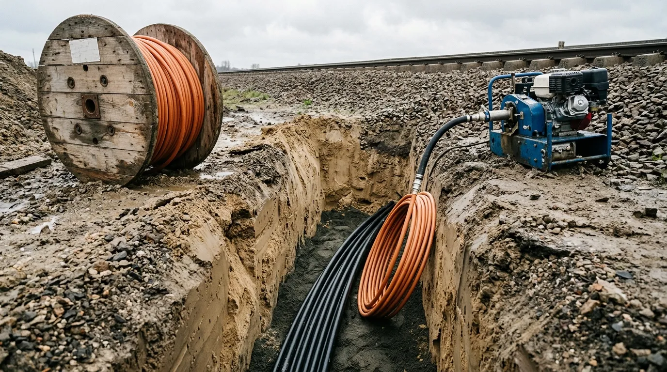
Duct installed once and fiber blown later decouples track access from capacity — which is why the civil work is the part worth doing properly.
Splicing, Closures, and Acceptance Testing
Joints belong in a joint bay or at a trough joint, not in the middle of a run. A closure has to survive the same water, fines and temperature cycling as the trough it sits in, while keeping every fiber inside its minimum bend radius. When you break fibers out of a 24- or 48-fiber cable to serve equipment, the splice protection and fiber management inside the closure decide whether that bay is still serviceable in ten years.
Identification matters more than it sounds. TIA-598 is the color code that lets the next crew find fiber 19 without re-testing the span, and cable, pigtails and closures should all follow it.
Test the installed link from both ends when bidirectional OTDR characterization is required by the project, especially for splice-loss evaluation and event location. In addition, perform end-to-end attenuation or insertion-loss measurements using the applicable installed-cabling method, and compare both the OTDR records and the loss results with the approved link budget and project acceptance limits. Build the loss budget from parts you can defend — fiber attenuation across the length, a budget per splice, connector losses, a repair margin, and a temperature allowance across the operating range. As an illustrative product benchmark, one publicly available datasheet for a cable marketed to the trackside cable standard family lists approximately 0.35 dB/km at 1310 nm and 0.22 dB/km at 1550 nm. Confirm the applicable attenuation requirement against the selected fiber specification, the current railway standard, and the approved project link budget. The number of splices is the term you control.
Record the route, not just the result: as-built drawings, a per-span OTDR trace and splice loss record, and a fiber allocation schedule. Without those, the second fault costs considerably more than the first.
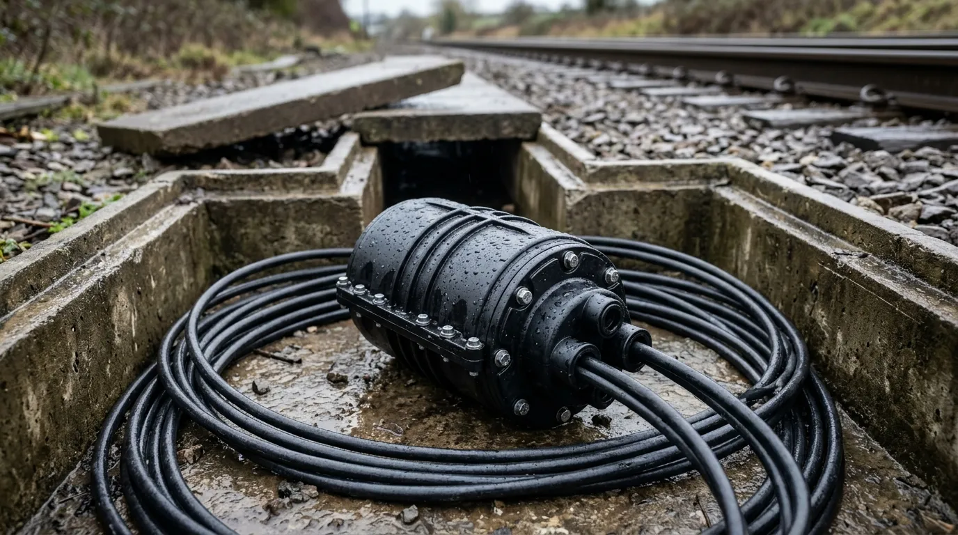
A closure inherits the trough's problems: standing water, temperature cycling, and fiber management that has to hold bend radius for decades.
One Fiber, Two Jobs: Communications and Sensing
The same route increasingly carries a second job. Distributed acoustic sensing turns the fiber into a sensor: an interrogator at one end sends light down the strand and reads back the tiny changes caused by vibration. With suitable cable placement, signal processing and application validation, DAS can support train detection or positioning, intrusion detection at a fence line, and monitoring of excavation activity near the cable. The construction that improves mechanical protection can also reduce acoustic or strain coupling, so a rugged communications construction may have lower sensing sensitivity than a cable designed for DAS.
This is why distributed acoustic sensing railway deployments appear in every trackside conversation — and why its cable requirements point in the opposite direction from everything above. The rail installation guidance published by the Fiber Optic Sensing Association is direct: sensing cable should be single-mode, tight-buffered or gel-filled loose tube, single-jacketed, and either unarmored or only single-armored, because heavy armor reduces acoustic coupling into the glass. Loose-tube designs with powder fill can damp the signal further.
The sensing span, spare-fiber interval, and detection range must be set by the DAS interrogator supplier and the project's sensing model rather than by a universal cable rule. FOSA guidance generally favors single-mode fiber, tight-buffered or gel-filled loose-tube constructions, a single jacket, and unarmored or single-armored designs where the mechanical environment permits. Cable position and installation method strongly affect acoustic coupling: place and protect the cable according to the target event, soil and structure conditions, required sensitivity, and the DAS supplier's test or commissioning plan. A cable close to the track may be effective for train-related vibration while being poorly placed for a different target such as trespass or excavation; do not assign a universal 3–5 m distance without project evidence. The construction trade-offs behind that requirement are set out in our tight-buffered vs. loose-tube comparison.
So the conflict is this: the threats above push toward heavy armor next to a running line, and sensing pushes toward the lightest jacket that will survive the route. If both duties are in scope, decide early — specify two cables for their separate jobs, or accept reduced sensing sensitivity on the armored one. Discovering it at commissioning, with a sensing vendor on site, is an expensive way to learn it.
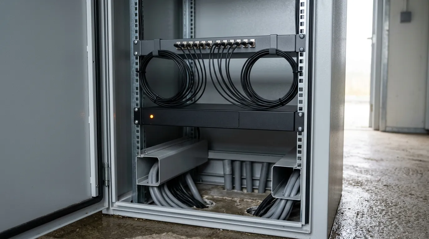
A sensing interrogator reads backscatter from the fiber, but detection performance depends on the interrogator, fiber and backscatter characteristics, cable construction, route placement, acoustic coupling and signal processing. The jacket is one design factor, not the sole factor that determines what the system can detect.
Specification Checklist for a Trackside Fiber Package
Work down this list and you have a package a supplier can quote and an infrastructure manager can approve.
Item | What to pin down |
|---|---|
Route and zones | Open line, tunnel, station, crossing — length in each, and where joints fall |
Access plan | What needs a possession, what is off-track, drum lengths |
Fiber type and count | Single-mode specification, working fibers plus spares and breakout allowance |
Buffer and water block | Loose tube or tight buffer, and the longitudinal blocking method |
Strength and jacket | Central member and yarns, jacket compound, halogen-free sections identified |
Armor | Steel tape, steel wire or all-dielectric — with the bonding consequence stated |
Mechanical ratings | Bend radius, crush, tensile, operating vs installation temperature |
Bonding and earthing | Every metallic element, its electrical continuity, and its approved bonding, earthing or isolation treatment at terminations and along the route |
Fire performance | Which standard applies to which section, confirmed by the infrastructure manager |
Sensing | In scope or not, and the jacket implication if it is |
Joints and closures | Closure type, splice protection, bays, fiber management inside |
Testing and records | Bidirectional OTDR where required, end-to-end attenuation or insertion-loss results, splice-loss records, approved loss budget, test wavelengths and reference method, as-built drawings, and fiber allocation |
Specifying several industrial sites at once? The industrial fiber optic cable guide covers the common selection logic — jacket, armor, temperature — that this list specializes for rail.
Five Mistakes That Cost More Than the Cable
Treating trackside as "outdoor." A generic outdoor cable has no answer for traction current, no answer for the access plan, and no answer for a tunnel section. The route defines the requirement, not the application name.
Armoring everything, then discovering sensing was in scope. Armor is the right answer to three of the eight threats and the wrong answer to one of the two jobs. Decide sensing before the cable is ordered.
Specifying the cable and leaving the route to the contractor. The route sets drum lengths, joint locations, the possession plan and the failure modes. A spec that names a cable and not a route has delegated the engineering.
Ignoring installation temperature and pulling tension. The installation range is narrower than the operating range, and the fiber is not supposed to take the load. Both are specified, not assumed.
Assuming the radio layer and the cable layer are the same project. The radio system serving trains, and its successor, have limits set by radio physics rather than maturity, and the migration is a years-long program. The backhaul fiber is where the capacity comes from — which argues for spare fibers in the cable you are about to bury, because it will outlive at least one radio generation.
FAQ
What is trackside fiber? Fixed optical fiber cable installed inside the railway boundary — along the open line, through tunnels, across station areas and at crossings — with the links from that route into signaling and telecoms equipment rooms. It carries the operator's backbone, signaling and train control data, station and crossing CCTV, and increasingly sensing traffic. It is not the radio link to the train.
Is trackside fiber different from ordinary outdoor fiber optic cable? The glass is largely the same family; most trackside cable is built to ITU-T G.652 single-mode. What changes is everything around it: the route, a cable standard owned by the infrastructure manager rather than the cable maker, separation and bonding against traction current, mechanical ratings for track machinery and settlement, and fire performance wherever the route enters a tunnel or confined space.
Does trackside fiber need to be armored? Not always — it depends on the route and on whether sensing is in scope. Armor defends against crush and rodents and may allow a route with no trough, but it introduces a metallic element whose bonding, earthing, isolation and surge-protection treatment must be defined by the approved railway electrical design. It may also reduce the sensitivity of a sensing system sharing the cable.
Can fiber replace trackside copper for signaling? It largely already has for communications and control. Where copper survives it is usually at legacy interfaces inside equipment, not along the route. The route-level case for fiber is the one to make: immunity of the dielectric transmission path to electromagnetic interference, no copper-style electrical distance limitation, and little intrinsic scrap value compared with copper. The actual optical reach is still limited by the link budget, dispersion, equipment, and system design.
How do you install trackside fiber without closing the railway? You do not entirely — off-loading, troughing and pulling need track access. The lever you have is route choice. A buried duct installed once and fiber blown in later moves most of the civil work into fewer possessions, and keeping joint bays off the running line keeps in-possession work to the shortest possible duration.
Next Step: Turn Your Route Into a Spec
Send us the route — zones, lengths, where the joints have to fall, and whether sensing is in scope — and the TTI Fiber engineering team will come back with a construction, a fiber count and a mechanical rating set that matches it. Our outdoor fiber optic cable range covers the armored, direct-burial and air-blown constructions these routes use, and we can quote against an infrastructure manager's own trackside standard rather than a generic outdoor datasheet.
If it is easier to start from the checklist, send us your route and splice schedule and we will work through the specification with you before anything is ordered.