FTTH Drop Cable Types: Flat, Round, Fig-8
Which FTTH Drop Cable Type Fits Which Route
FTTH drop cable types divide three ways, and the route decides between them long before the model code does: flat bow-type for the run down a wall, round water-blocked cable for a duct or buried conduit, and figure-8 self-supporting for an aerial span between a pole and the building. A fourth case sits between them — flat cable lashed to an existing strand — which is an aerial method using a cable that is not itself aerial. None of that tells you what the cable has to survive, so this page runs four constraints that eliminate options, then gives you the numbers to put on the purchase order and the failure each one prevents.
Why the Model Code Decides Nothing
Four letters-and-digits strings get quoted on drop-cable purchase orders every day: GJXH, GJXFH, GJYXCH, GJYXFCH. They look like specifications. They are not. They come out of the Chinese YD/T 1258 model-code convention, which encodes structure and little else: GJ the drop-cable family, X a bow-type (flat, butterfly) cross-section, F FRP — non-metallic — strength members, with steel wherever that F is absent, Y the self-supporting outdoor variant (a GJY* prefix), C a figure-8 profile with an integrated messenger, and the trailing H a halogen-free (LSZH) sheath. Read that grid strictly and the four codes come out as: GJXH — flat bow-type, steel strength members, LSZH sheath, not self-supporting; GJXFH — the same cable all-dielectric; GJYXCH — a self-supporting figure-8, LSZH sheath, steel strength members and a steel messenger; GJYXFCH — the same construction with FRP strength members instead of steel.
What the code does not fix is everything a buyer needs to order against: no tensile load, short- or long-term; no bend radius; no crush resistance; no fiber grade; no fire class. H says halogen-free and nothing about which reaction-to-fire class the compound actually reaches; nothing in the string names a CPR class at all. And the letters are applied loosely in the trade, which is the real difficulty — the figure-8 datasheet cited below is titled GJYXCH, specifies an LSZH jacket as standard and offers PE only as an option. A code names a family, not a cable.
The proof is in two datasheets that both describe a legitimate flat drop cable for the same last-mile job. A Corning 2-fiber indoor/outdoor flat drop is specified at 400 N long-term and 1350 N short-term tensile, with an 80 mm minimum operating bend radius and a 10.1 × 4.4 mm profile. A figure-8 self-supporting drop from ERA Fiber, in its 2-fiber reference build, is specified at 300 N long-term and 600 N short-term, with a 2.0 × 5.0 mm body, and it needs the messenger wire to reach even that. Same application, same "drop cable" category, and the ratings sit 2.2× apart — but they are not two measurements of the same thing. The Corning number is an installation rating carried by non-metallic (FRP) strength members — this particular build is the toneable variant, whose copper tracer is a locating aid, not a strength member: 1350 N is what the cable must survive while it is pulled and lashed into place, and 400 N is what it may then hold permanently. The ERA number is a working rating for the messenger assembly: 600 N short-term and 300 N long-term is the load that messenger, its clamps and its sag are allowed to carry across a span, with the fiber body carrying none of it. Strength-member material and diameter set the first figure; whether the cable holds its own span or hangs on something else's sets the second. Two codes of the same length tell you neither.
So the model code is not a specification, and a PO that carries only a code will be satisfied by whichever construction the supplier has on the shelf that week. What follows is the alternative: four constraints that actually eliminate options, applied to the three constructions that divide the market — flat bow-type, round, and figure-8 self-supporting. Where this page stops, the FTTH and PON deployment guides hub picks up with topology, split ratio and loss budget.
Four Constraints That Pick the Cable
Every drop-cable decision is a collision between four physical facts about the route. Run them in order; each one deletes options rather than scoring them.
Constraint | The question | What it eliminates | Figure to check |
|---|---|---|---|
Bend radius at the entry | How tight is the tightest permanent bend — wall entry, skirting, ONT tray? | Standard G.652 fiber, thick round cable | Cable bend radius in mm, plus fiber grade G.657.A1 or A2 |
Tensile load | Is the cable carrying its own span, or being pulled? | An indoor-only jacket on an aerial span; any cable pulled hard through a duct | Short-term and long-term tensile, in N |
Water and UV | Does the run stay wet, or stay in the sun? | Indoor-only jackets outdoors; non-water-blocked cable in a flooded duct | Jacket material, water-blocking construction, UV stabilization |
Labor at both ends | Who terminates it, with what tool, at each end? | Constructions that need a splicer at the customer's wall | Termination method, connector type, cable-end preparation |
The order matters. Bend radius is first because it is the constraint that most often gets discovered after installation, when the drop is already stapled to a skirting board and the loss shows up as lost margin at 1550 nm. Tensile is second because it is the only one that can fail catastrophically — a cable loaded past its long-term rating does not degrade gracefully, it necks, and the fiber inside follows. Water and UV are third because they fail slowly over years rather than at turn-up. Labor is last only because it is the constraint that can be re-planned; it is usually the one that decides cost.
One of those four is a fiber question rather than a cable question, and it is the one most often specified last. ITU-T G.657 defines the bend-insensitive single-mode categories by macro-bending loss at a stated radius — in practice, G.657.A1 for bends down to roughly a 10 mm radius and G.657.A2 for 7.5 mm. That is the difference between a drop that survives a tight wall entry and one that needs a purpose-made corner guide.
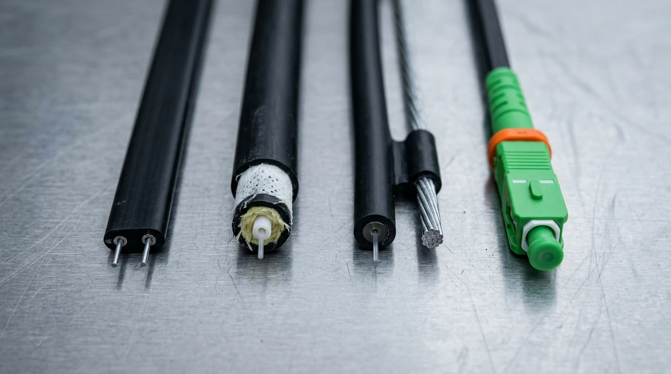
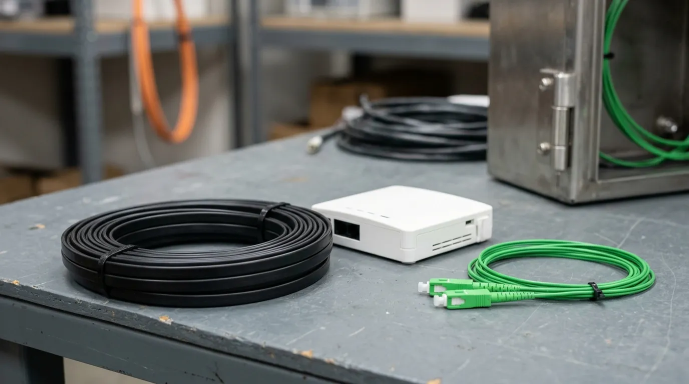
The four objects this page compares, cut clean so the insides are visible: flat bow-type with its two parallel strength members, round duct cable with its water-blocking layer, figure-8 with the messenger that carries the span, and a factory-terminated flat drop.
Flat Bow-Type: The Default, and Where It Stops Working
The flat bow-type cable — "butterfly" in workshop slang — is what most FTTH subscribers in Europe and Asia have on their skirting board. Two parallel strength members run either side of a 250 µm fiber (or two), and the whole assembly is extruded into a flat jacket roughly 2 × 3 mm, notched so it splits open by hand.
Its advantages are all labor advantages. It strips with a cheap drop-cable tool, it accepts a field-installable fast connector without a splicer, it clips flat against a wall with the right clip — staples crush it — and it coils into a tight loop in a customer's ONT tray. On volume, that is the whole ballgame: the construction that terminates fastest per drop wins the residential market, and this one does.
Its limits are equally structural.
It carries almost no tension. The strength members exist to stop the fiber being stretched while the jacket is handled, not to hold a span. Put one across a gap between a pole and a wall and the installation may pass, then fail in the first winter: the jacket creeps, the fiber sees strain, and loss climbs at the coldest part of the year. Aerial work needs a load path a flat cable does not have — either the figure-8 construction in the next section, which brings its own messenger, or an existing strand to lash it to. A flat cable with a steel wire inside it has neither.
Lashed, not suspended. Lashing a flat indoor/outdoor drop to an existing strand is ordinary aerial practice wherever strand is already up: Corning lists Aerial among the installation methods of the flat indoor/outdoor drop quoted above, and that cable's strength members are dielectric, not a messenger. Nothing in the cable body holds the span — the strand does, and the drop only has to survive the lashing tension, the clamp loads and its own weight between supports. Two consequences follow. Span, sag and clearance belong to the strand and to whatever structure it hangs off, so they are inherited rather than specified. And the failure modes change to chafe at a clamp, corrosion of the lashing wire, and UV on a jacket that was chosen for a wall.
It does not like long duct pulls. A flat profile in a round duct presents an edge to the wall, twists when it is pulled, and the twist is what converts pull tension into sidewall pressure at every bend. Round cable exists for exactly this reason.
Within the flat family, the material choice matters more than the code. Strength members are either steel (stiffer, cheaper, metallic, needs bonding or earthing where the local code says so) or FRP (all-dielectric, no earthing question, slightly more expensive). The fiber is G.657.A2 where the route has genuinely tight corners and G.657.A1 everywhere else — A2 costs more and buys tolerance you may not need if every drop ends on an outside wall with a generous loop.
There is a third variant worth knowing because it is spreading indoors: the invisible or transparent drop. Same bow-type body, clear jacket, often a thinner fiber coating, chosen because it can run along a white skirting or a door frame and be almost unseeable. It is an interior FTTR answer, not a fourth outdoor construction — it inherits every flat-cable limit, losses UV resistance early, and is not a cable to run on a façade. The invisible cable installation guide covers the routing practice, and fast-connector termination covers what happens at the room end.
Round Drop Cable: Duct, Conduit and the Pull
Round drop cable puts the fiber in a central tube or a tight buffer between two strength members, under a round PE or LSZH sheath, typically 5 to 6 mm outside diameter. It is not a flat body sleeved into a tube: the strength members bear on a round core, which is what keeps the profile round under a pull. It costs more per meter than flat cable and it repays that in the duct.
Friction and twist. A round profile contacts a round duct on a line, not on an edge, so it does not corkscrew as it is pulled and it does not convert tension into sidewall pressure. That matters over distances where a crew cannot push: a 40 m duct pull with two 90° swept bends (a typical access-run length, not a specification) is routine for round cable and a bad afternoon for flat.
Water. Buried ducts fill. A drop that sits in standing water needs a water-blocked core — dry water-swellable tape in most modern constructions, gel in older designs — and a sheath that will not wick. This is the single most common omission when a flat indoor cable is substituted into a duct "because it was on site": nothing in the flat construction stops water travelling along the core to the splice.
Rodent and crush. A thicker round sheath buys sacrificial material against gnawing and against the crush of a duct that has been driven over. It is not armor — cable that needs real protection belongs in the underground and buried cable family, in a duct or with armor, not in a thin drop sheath. For buried routes, the toneable variant is worth the small premium: it carries a detectable tracer so the drop can be located from the surface without excavation.
Bend in a swept duct. Round cable has a larger minimum bend radius than a flat bow-type body, and that cuts both ways: it will not accept the 10 mm corner at the building entry, so most duct routes end with a transition — round cable to a wall box, flat cable from the wall box to the ONT. Designing that transition is part of the duct option's cost, and it is the detail that most often gets left out of the quote.
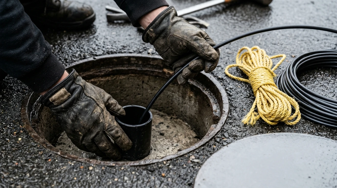
The duct route's labor profile in one frame: rodding, a pull rope, cable lubricant and two people — the cost that decides duct economics long before the cable price does.
The engineering discipline the duct route needs is measurement, not assumption: prove the duct with a mandrel and a rod first, pull with a tension gauge rather than by feel, and record the pull tension. A cable pulled to twice its short-term rating passes the acceptance test on the day and fails inside two years.
Figure-8 Self-Supporting: The Messenger Does the Work
The figure-8 construction is a flat bow-type body extruded in one jacket with a steel messenger wire, joined by a thin web, so the cross-section looks like an 8. That messenger is the whole point: it carries the span load, and the fiber body carries none.
The distinction between the messenger and the strength members is the one most often blurred in supplier literature. The two strength members in the flat body protect the fiber from handling and from the clamp; the messenger in the web above is what holds the cable between the pole and the building. A cable with FRP strength members and no messenger is not "self-supporting" in any sense that matters outdoors.
The published figures for one 2-fiber reference build make the trade visible: 300 N long-term and 600 N short-term tensile on the steel messenger, 1000 N/100 mm long-term and 2200 N/100 mm short-term crush, a 15 mm static and 30 mm dynamic minimum bend radius for the cable body once the messenger is removed, and a typical pole-to-building span of 50 m, extendable to about 80 m with a 1.2 mm messenger and controlled sag. Compare that with the 400 N long-term, 1350 N short-term dielectric drop quoted earlier and the reason to own both becomes obvious: one number is a load the cable has to survive for an hour, the other is a load the messenger has to hold for twenty years, and neither is a stronger version of the other.
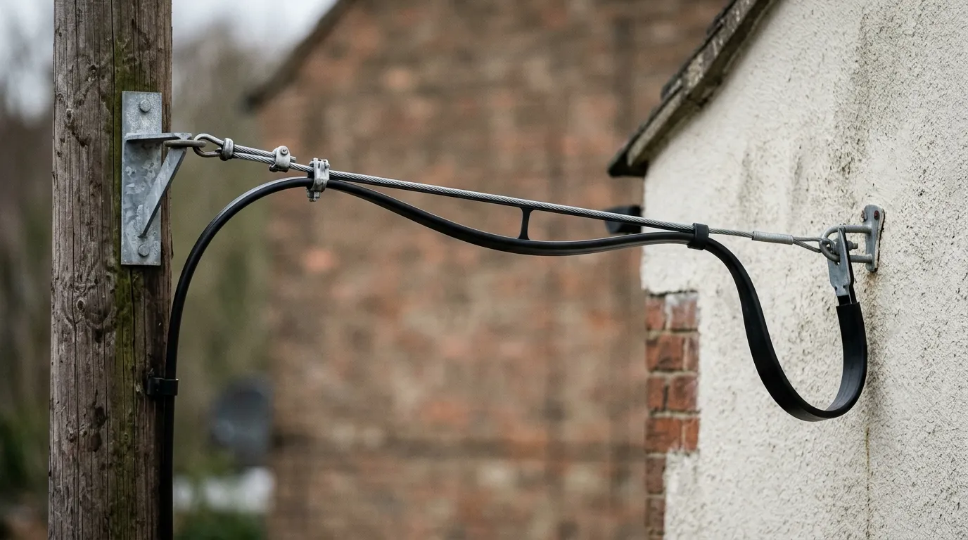
Where the load goes: the messenger wire carries the span from pole bracket to wall anchor, and the flat cable body hangs from it with no tension on the fiber.
Three practical rules follow.
- Span is a calculation, not a catalogue number. The 50 m figure is a typical working value for a standard messenger; ice load, wind load and local clearance rules all move it, and the messenger, the clamp and the pole attachment have to be sized together.
- The messenger must be earthed where the local code requires it. The steel messenger makes the cable metallic. If the route cannot accept a metallic path, the dielectric variant (FRP messenger, FRP strength members) is the answer, at a span penalty.
- Tear-off is a design decision. At the wall entry the messenger is stripped off the web and the flat body continues indoors. Where that happens, whether the messenger terminates on a bracket or continues to the next pole, and how the entry is sealed, are all decisions that should be on the drawing rather than made by the crew.
The drop also has to land somewhere. On most networks that is a distribution box rather than a splice pit, and FAT versus FDT access cabinets sets out how the port count at that box constrains the drop plan.
Self-Supporting vs Duct vs Aerial: The Routes Compared
Aerial and duct are not cable types; they are installation methods, and the cable follows from them. Laid out side by side, the practical routes look like this — and aerial splits in two, because a drop can either carry its own messenger or hang from a strand that is already there.
Figure-8 aerial | Lashed to existing strand | Duct / buried conduit | Direct-to-wall (flat) | |
|---|---|---|---|---|
Cable | Figure-8 self-supporting, steel or FRP messenger | Flat indoor/outdoor, dielectric strength members, no messenger | Round, water-blocked, 5–6 mm | Flat bow-type, G.657.A1/A2 |
Span limit | ~50 m typical, ~80 m with a 1.2 mm messenger | The strand's span and sag; the cable only sees lashing, clamp and self-weight load | Length limited by duct, rodding and pull tension | Wall-run only; no span |
Hardware | Pole clamp, dead-end, wall bracket, entry seal | Lashing wire or figure-8 lashing, support clamps, strand hardware, wall bracket | Handhole, duct plug, wall box, transition to flat | Clips, corner guides, wall entry, NID |
Crew profile | Two-person, ladder or bucket, live pole access | Two-person with a lashing tool, ladder or bucket, strand access | Two-person plus rodding and pull gear; civils if the duct is new | One installer, hand tools |
Failure mode | Messenger corrosion, clamp slip, wind/ice load | Lashing-wire corrosion, chafe at a clamp, UV on the jacket | Water ingress, rodent, crush, pull damage | Bend at the entry, staple crush, UV on an indoor jacket |
Best fit | Pole-to-building where the duct does not exist | Where a strand already exists and no poles are usable | Pre-ducted areas, MDUs with existing conduit, dense urban | Short runs from an existing box to the wall |
The comparison that actually decides tenders is not the cable price — it is which column avoids civil work. Aerial wins where poles already exist and the local authority allows attachment. Duct wins where the conduit is already in the ground and a crew can rod it. Direct-to-wall wins only when the access point is close, and it is the column most often overused: a flat indoor cable stapled along a 40 m façade is not a cheaper aerial drop, it is a future fault.
Aerial splits along a commercial line before a technical one. Figure-8 needs poles, or a licence to attach to them; lashing needs an existing strand, which in most retrofit markets is legacy copper or cable-television plant the operator already has rights over. That inherited right, not the cable, is usually what makes the lashed column the cheapest way onto a building in a US suburb — and the reason a flat drop with a 400 N long-term rating turns up on aerial plant at all.
The Numbers to Put on the PO
The cure for the model-code problem is a specification line that states what the cable must survive. Seven fields do most of the work, and each has a direction of acceptance.
Field | What to write | Acceptance direction | Why |
|---|---|---|---|
Tensile, short / long term | Two numbers in N, per construction | At or above the route's calculated load, long-term with margin | Long-term is the rating that governs service life; short-term only covers installation |
Crush | N per 100 mm, short and long term separately | Above the clamp and duct load it will see, judged on the long-term figure | Clamp pressure is the usual cause of a "dead" drop |
Bend radius | Cable radius in mm, static and dynamic | Compatible with the tightest real bend, or specify a corner guide | Operating radius, not installation radius |
Fiber grade | G.657.A1 or G.657.A2, ITU-T reference | A2 only where the radius demands it | A1/A2 differ in the bend they tolerate, not in attenuation class |
Attenuation | dB/km at 1310 and 1550 nm, maximum | At or below the G.652 class limit for the grade specified | The cabled value is always worse than the fiber value — specify the cable |
Jacket and fire class | Material plus class: LSZH with a CPR class for indoor legs, PE with UV stabilization for outdoor | Class named, certificate requested | In the EU, cable jackets sold as construction products are CE-marked under the Construction Products Regulation 305/2011, with the reaction-to-fire class coming from the EN 50575 harmonised standard |
Operating and installation temperature | Two °C ranges, not one | Inside the local climate envelope, with the installation range checked separately | Cold-weather handling is a limit on the crew's day, not on service life |
The jacket row is where indoor and outdoor legs must be separated rather than compromised. A drop that crosses the building line needs two constructions or a defined transition point, not a single cable with an optimistic description. The CPR cable classes guide has the class-by-class detail.
Every row above is testable, which is the point. "Good quality drop cable" is not; "400 N long-term tensile, 80 mm operating bend radius, G.657.A2, a stated maximum attenuation at both PON wavelengths, and LSZH with its CPR class" is. Name the test basis too — the mechanical and environmental methods behind those figures are the IEC 60794 series, so the acceptance record should say which one was used rather than only that a test was passed.
Fiber Count and Termination
Fiber count is usually decided for the wrong reason — by what the warehouse has — and then justified afterwards.
One fiber is the minimum and is increasingly rare: it leaves nothing to switch to when the strand fails.
Two fibers is the practical default for a residential drop. One is live, one is the spare that turns a fault into a re-patch instead of a re-pull. Almost every figure quoted in this article is a 2-fiber reference build for that reason.
Four fibers appears where a single drop serves a small MDU or a home office on a separate physical path, or where the operator wants headroom for a future second carrier.
Twelve fibers belongs to a riser or a multi-dwelling distribution run, where the "drop" is really a short distribution cable. If a planner is specifying 12-fiber flat cable for a single-family drop, the design has probably confused distribution with drop.
Termination is the other half of the decision, and it splits three ways:
- Pre-terminated (factory connectorized) — highest first-cost, lowest skill requirement on site, and the only option where the endface is tested in the factory and arrives with the test record. Length must be ordered per drop, so the measuring is on you.
- Field-installable fast connector — no splicer, one tool, a few minutes per end. The trade is a higher per-connection loss allowance and a result that depends on the installer's cleave.
- Fusion-spliced pigtail — best loss and the most durable joint, but it needs a splicer and a mains supply at the customer's wall, which is exactly what most residential drops do not have.
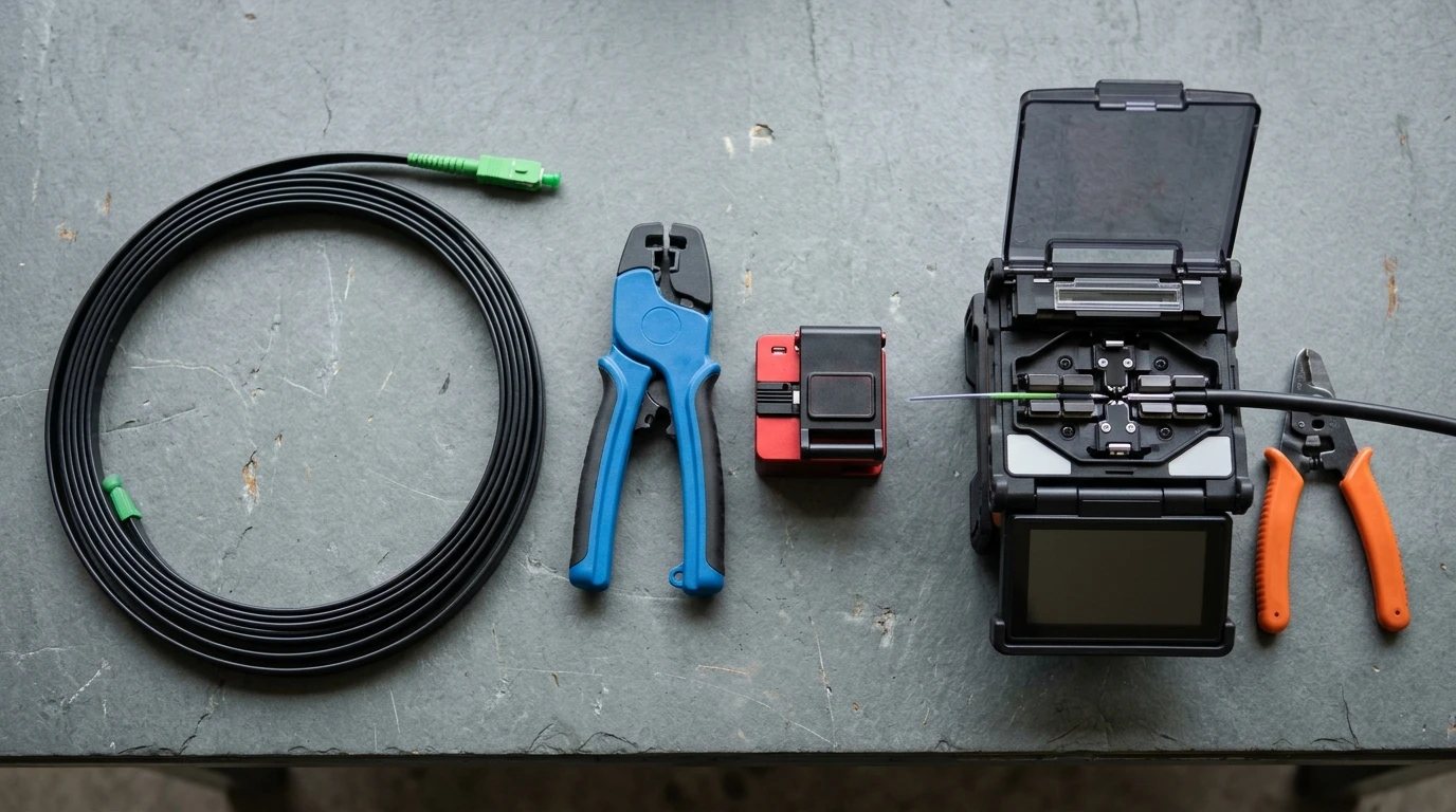
The three termination decisions, left to right: factory connectorized and capped, field-installed with a cleaver and an assembly tool, or spliced to a pigtail in a machine.
Whichever is chosen, the specification should state maximum insertion loss per mated pair, minimum return loss, and the endface acceptance criterion by standard rather than by adjective. On a PON the drop terminates on SC/APC, and mixing polish is the classic field error — APC versus UPC explains why the angled contact exists. Connector loss is also where the drop's own budget contribution concentrates: budget a typical mated APC pair at 0.30 dB and a field-installed fast connector at 0.50 dB — planning values, not a specification, so take your own from the connector datasheet or from the IEC 61753-1 grade you specified — and two ends chosen one way versus the other is a 0.4 dB difference on every subscriber — trivial against a 1:32 splitter, decisive on a marginal route that is already close to the budget class defined in ITU-T G.984.2.
Cost per Drop: What Moves the Number
Nobody should take a per-meter price from a web page, including this one. What can be compared honestly is the structure of the cost, because the same five drivers apply to every route and only their weights change.
Cost driver | What it is | Figure-8 aerial | Lashed to strand | Duct | Direct-to-wall |
|---|---|---|---|---|---|
Cable per meter (index) | Purchase price per meter, by construction | Highest (messenger included) | Low (no messenger) | Middle | Low |
Hardware per drop (index) | Clamps, brackets, boxes, entry seals | Pole clamp + bracket + seal | Lashing wire, support clamps, bracket + seal | Box + plug + transition | Clips + entry + NID |
Installation labor (index) | Crew hours per drop, including access | Two-person, access equipment | Two-person, lashing tool, access equipment | Two-person, rodding and pull gear | One installer |
Termination labor (index) | Per end, by method chosen | Same for all four | Same for all four | Same for all four | Same for all four |
Scrap and rework (index) | Cut waste, wrong lengths, re-pulls | Low (order per span) | Low–middle (strand lengths are known, cuts are measured) | Middle | Highest (walls are measured late) |
Read the table as a template: replace each index with your own quoted numbers and the ranking falls out. In most tender comparisons the cable line is the smallest of the five, which is why a nominal 15 percent saving on cable per meter (illustrative, not a quoted figure) rarely survives a change of route — the labor and access lines move more than the material line ever will.
Two costs that never appear on the quote and always appear in year three: re-pulls caused by a construction that did not fit the route, and truck rolls caused by an indoor jacket that was asked to do an outdoor job. Both are consequences of the choice made on this page, not of the supplier's price.
The Selection Table
Read this as the short version of the page: for each route condition it names the FTTH drop cable type, the fiber count, the jacket and the termination, and every row is a decision the four constraints have already made. Where two rows look interchangeable, the difference is in the hardware line, not in the cable.
Route condition | Construction | Fiber | Jacket | Termination |
|---|---|---|---|---|
Pole to building, no duct, span under ~50 m | Figure-8 self-supporting, steel messenger | 2 | PE, UV-stabilized | Pre-terminated or fast connector |
Same, but no metallic path permitted | Figure-8 self-supporting, FRP messenger | 2 | PE, UV-stabilized | Pre-terminated |
Strand already in place, no poles usable | Flat indoor/outdoor, dielectric strength members, lashed to the strand | 2 | PE, UV-stabilized | Pre-terminated or fast connector |
Existing duct or conduit, run over 30 m | Round, water-blocked | 2 (4 for MDU) | PE | Fast connector or pigtail |
Direct-buried, no duct available | Round, water-blocked, armored or toneable | 2 | PE | Pigtail splice or pre-terminated |
Access box to wall, under 30 m, indoor | Flat bow-type | 2 | LSZH, CPR class | Fast connector |
Interior route on visible skirting | Flat, transparent (invisible) | 1–2 | LSZH | Fast connector |
MDU riser serving several units | Flat or round, 4–12 fiber | 4–12 | LSZH, CPR class | Pigtail splice at both ends |
The drop is one line on a larger document. Sizing the whole FTTH bill of materials shows where that line sits, and how the drop quantity falls out of homes passed and average drop length rather than out of take-up.
FAQ
Which drop cable type is best for an aerial span?
Figure-8 self-supporting with a steel messenger, sized to the calculated span load rather than to a catalogue span. A 2-fiber reference build is typically rated at 300 N long-term and 600 N short-term on the messenger and works to about 50 m between pole and building, with roughly 80 m achievable using a 1.2 mm messenger and controlled sag. Where strand is already up and poles are not, the same route is served by a flat indoor/outdoor drop lashed to the strand — but a flat drop cannot carry its own span, whatever its tensile rating says.
Is G.657.A2 necessary, or is A1 enough?
A1 is enough where every permanent bend stays above roughly a 10 mm radius, which is most drops that terminate on an outside wall with a service loop. A2 buys tolerance down to about 7.5 mm and is worth it where the route goes behind skirting, through a tight wall entry, or into a shallow ONT tray. The cost difference is small per drop and the rework cost of getting it wrong is not.
How long can a figure-8 drop span?
That is a calculation, not a datasheet line: span follows messenger size, clamp type, ice and wind load, and the clearance rules that apply locally. The ERA datasheet gives ≤50 m for the standard build and up to about 80 m with a 1.2 mm messenger and controlled sag. Longer than that, the design has moved from a drop to a mini-span or an ADSS route.
What belongs on the drop-cable PO line?
Tensile in newtons (short and long term separately), crush in N/100 mm, static and dynamic bend radius in mm, fiber grade with the ITU-T reference, maximum attenuation at 1310 and 1550 nm, jacket material with its fire class, operating and installation temperature ranges, messenger material and diameter, fiber count, and the termination method. The model code can go on the PO as well — as a description, after the numbers, not instead of them, and it is the same line whichever of the FTTH drop cable types you settled on.
Where TTI Fiber Fits
Most of this page is arithmetic a competent planner can run without a supplier. What a supplier controls is whether the numbers on the PO are the numbers delivered: which tensile class a given construction is actually built to, whether the messenger is galvanized or phosphated, whether the fiber is really A2, and whether the test report states its method. TTI Fiber manufactures flat, round and self-supporting FTTH drop cable in 1- and 2-fiber builds, with FRP or steel strength members and LSZH or PVC jackets; the useful conversation at quotation stage is not price per meter — it is which figure each construction will be held to, and what evidence arrives with the drum.