FTTH BOM Checklist: Sizing Every Line Item

What Belongs on an FTTH BOM Checklist
An FTTH BOM checklist fails for one of three reasons. A line item is missing. A quantity was sized from the wrong input. Or the part that arrives is not the part the design assumed. None of those is a pricing problem, and none of them shows up in a tender comparison. They show up in week six, when the closure is already on the pole and the pigtails are still on a ship.
So this checklist runs on one rule: every line carries a unit, a sizing input, and a loss figure. A line with a unit but no sizing input gets ordered twice. A line with a sizing input but no loss figure quietly spends optical budget that the splitter ratio was supposed to have.
Ten material families actually appear on a last-mile PON bill of materials, and they are the same ten whether the document in front of you is called an FTTH materials list or a BOM:
- Cable — feeder, distribution and drop, in three different constructions.
- Splice closures — dome, in-line and cabinet-mounted, plus their trays and protectors.
- Splitters — PLC modules, splitter trays, shelves, and the housing they sit in.
- Access terminals — FDB, FAT or NAP boxes, with the port count that lets a drop land.
- ODF and patch panels — the central-office end, loaded or empty.
- Connectors, adapters and pigtails — the smallest lines and the ones most often short.
- Patch cords — CO-side and customer-side, in the right polish.
- ONT/ONU and customer hardware — the active CPE, its power supply, the internal outlet.
- Aerial, duct and wall hardware — clamps, brackets, messenger grips, duct plugs, wall entries.
- Test equipment, cleaning consumables and labels — the family that decides whether you can hand the network over.
One boundary worth drawing before the table, because it is where two documents collide. Route construction — duct, trench, aerial strand, pole hardware on the line itself — belongs to the outside-plant bill of materials. If your project has both, keep them as two documents that meet at the ODF and at the first closure; the OSP project BOM breakdown covers the civil and aerial side. What follows starts at the OLT patch panel and ends at the customer's ONT.
The FTTH BOM Checklist by Network Segment
The structure that survives procurement review is the one that follows the physical path. Build the table in segments, and every quantity has one obvious owner, one obvious input, and one obvious place to check it. This document sits inside a wider set of decisions — the FTTH and PON deployment guides index covers topology, split ratio, closures and testing as separate design steps, and a BOM is only as good as the design it is counting.
Segment | Line items | Unit | Sizing rule |
|---|---|---|---|
Central office / OLT | ODF frame, adapter plates, pigtails, PON patch cords, OLT cards, SFP optics | ports, pcs | ODF ports = feeder fibers × 1.2; patch cords = PON ports × 1.1 |
Feeder | Outdoor cable (loose tube, usually 48F or 96F), closures, splice protectors, route reserve | m or km, pcs | route length between splice points × 1.05; one closure per drum joint or branch |
Distribution | Cable (12F to 48F), closures, FDBs, trays, pigtails, adapters | m or km, pcs | one fiber per drop port; runs = drop ports ÷ cable fiber count |
Access point | FDB/FAT box, adapter plate, splitter tray, drop pigtails | pcs, ports | ports = homes passed × 1.15 |
Drop | Flat or round drop cable, pre-terminated assemblies, clamps, wall entry, NID | m, pcs | homes passed × average drop length × 1.08 |
Customer premises | ONT, power supply, patch cord, internal outlet, labels | pcs | one per activated subscriber, not per home passed |
Common | Splitter modules, splice protectors, cleaning kit, test cords, labels | pcs | per splitter position and per splice count |
Two rows in that table carry most of the risk, and neither is the expensive one. The access-point row is where port count gets rounded down "because take-up is only 60 percent". The common row is where the splice protectors, adapters and test cords live — the items that cost almost nothing per unit and stop a crew dead when they run out.

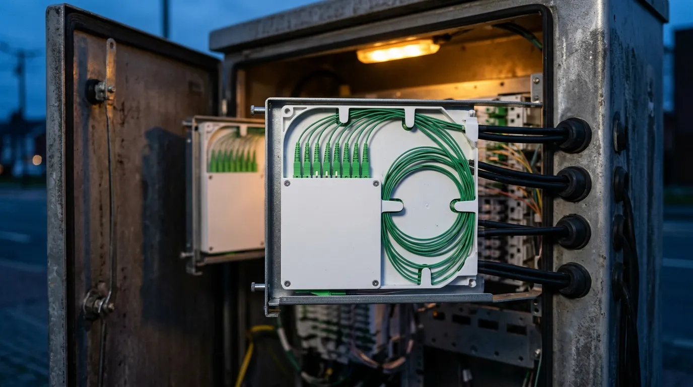
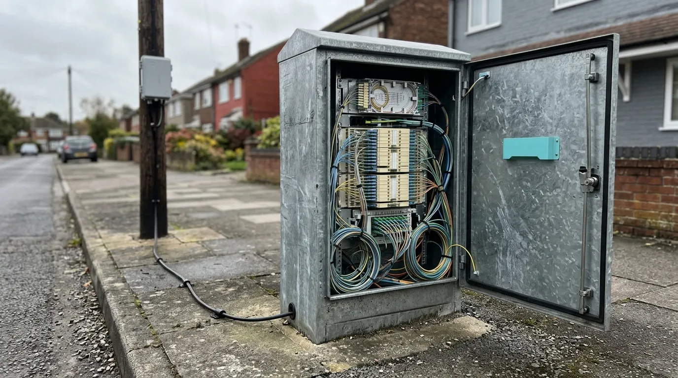
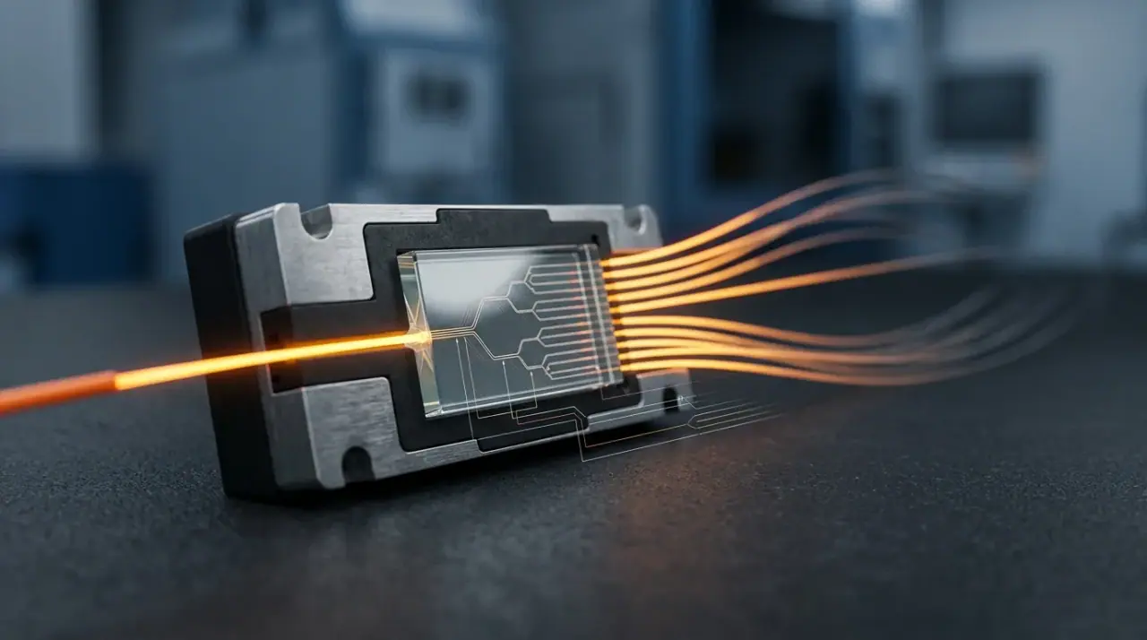
The BOM follows the light: OLT and ODF at one end, closure and distribution box in the middle, drop cable into the home. Each object on this bench is a segment in the table above.
How Quantities Fall Out of Subscriber Count and Split Ratio
Almost every quantity in an FTTH bill of materials descends from two numbers — homes passed and split ratio — plus one commercial assumption you should write down rather than carry in your head: take-up.
Take a reference serving area of 1,000 homes passed, 60 percent take-up at year two, GPON with 1:32 centralized splitters, four street cabinets, an average drop of 55 m and an average distribution run of 400 m from cabinet to access point. Every figure below is derivable from those six inputs, which is the point: hand the same six numbers to a second engineer and the BOM should come back the same. It is also what makes the table usable as an FTTH BOM template — replace the six numbers and the structure still holds.
Line item | Rule | Inputs | Order quantity |
|---|---|---|---|
PON ports | homes passed ÷ split ratio | 1,000 ÷ 32 = 31.25 | 32 ports (2 × 16-port cards) |
1:32 PLC splitters | PON ports + 2 spare | 32 + 2 | 34 |
FDB ports | homes passed × 1.15 | 1,000 × 1.15 = 1,150 | 74 boxes × 16 ports (2 spare) |
Street cabinets | 1 per planned cabinet, +1 spare | 4 + 1 | 5 |
Drop cable | homes × avg drop × 1.08 | 1,000 × 55 m × 1.08 | 59.4 km on 2 km drums |
Drop clamps and wall entries | 1 per drop, +10% | 1,000 × 1.10 | 1,100 |
Distribution cable 48F | (drop ports ÷ 48) × avg run × 1.05 | 24 runs × 400 m × 1.05 | 10.1 km |
Feeder cable 48F | cabinets × route length × 1.05 | 4 × 1.2 km × 1.05 | 5.0 km |
Splice closures | drum joints + branch points + 2 spares | 12 per route plan | 14 |
Pigtails | 2 per splitter output port, +5% | 2,048 × 1.05 | 2,150 |
Adapters | 1 per pigtail, +5% | 2,048 × 1.05 | 2,150 |
Splice protectors | 1.15 per splice | 2,048 splices | 2,355 |
ODF ports | feeder fibers × 1.2 | 192 × 1.2 = 230 | 2 × 144-port frames |
PON patch cords | PON ports × 1.1 | 32 × 1.1 | 36 |
ONT + power supply | 1 per activated subscriber, +5% | 600 × 1.05 | 630 |
Acceptance test kit + labels | 1 set per crew, +25% | 4 crews × 1.25 | 5 sets |
Three of those rows are the ones a bill of materials usually loses: the customer-side hardware, the drop clamps that hold the cable to the wall, and the test kit that proves the link at handover. The first two come straight out of the six inputs. The test kit does not — it is one set per crew, so write the crew count down as a seventh input before the table is finished.
Read the first two rows together, because that pairing is where a project breaks. Splitters are sized on homes passed; PON ports are sized on splitters. At 60 percent take-up the two numbers diverge: 600 subscribers need 19 splitters' worth of active ports, but the build has to pass 1,000 homes, so 32 splitters are installed and 34 ordered. Short that order to 19 and 392 homes passed have no port to be activated into — and the repair is not a re-order, it is a truck roll, a cabinet opening, a splice and a service interruption for the 32 subscribers already live on that splitter.
The reverse error is just as common and cheaper only in the short term: ordering splitters to the take-up figure while also ordering FDB ports to the take-up figure. Then year three arrives, take-up climbs, and both the splitter port and the drop port are missing at the same address.
Three further consequences of the arithmetic:
Distribution fiber count is set by drop ports, not by subscriber count. In a centralized design each FDB port needs its own fiber back to the splitter output. A 48F distribution cable therefore serves 48 drop ports; 1,150 drop ports need 24 runs of it, and a 12F cable in that position is a design that expires at 12 subscribers per run.
Take-up changes the active list, not the passive list. ONTs, customer patch cords and power supplies are sized on activated subscribers — 600 in year two. Cable, closures, splitters, FDBs and ODF ports are sized on homes passed. Mixing the two bases is what produces a warehouse full of ONTs and a shortage of drop clamps.
Split ratio is the lever on total cost, and it is a loss decision first. Moving from 1:32 to 1:64 halves the splitter count and the PON port count, and adds about 3.5 dB of insertion loss on every subscriber path. Whether that trade is available depends on the route and the optics class, not on the price list — the splitter ratio selection method works that subtraction line by line, and the two-stage splitting design guide covers what a cascade does to the same arithmetic.
A cascade is worth its own line in the BOM, because the component count changes with the topology. Two stages of 1:4 and 1:8 deliver the same 32 ports as one 1:32 module, but the order becomes five modules instead of one, plus two more mated connector pairs per path. That is 0.8 dB of extra splitter loss, plus about 0.6 dB from the two extra connector pairs — 1.4 dB in total, the reason a cascaded area needs its own loss check rather than an assumption inherited from the centralized one.
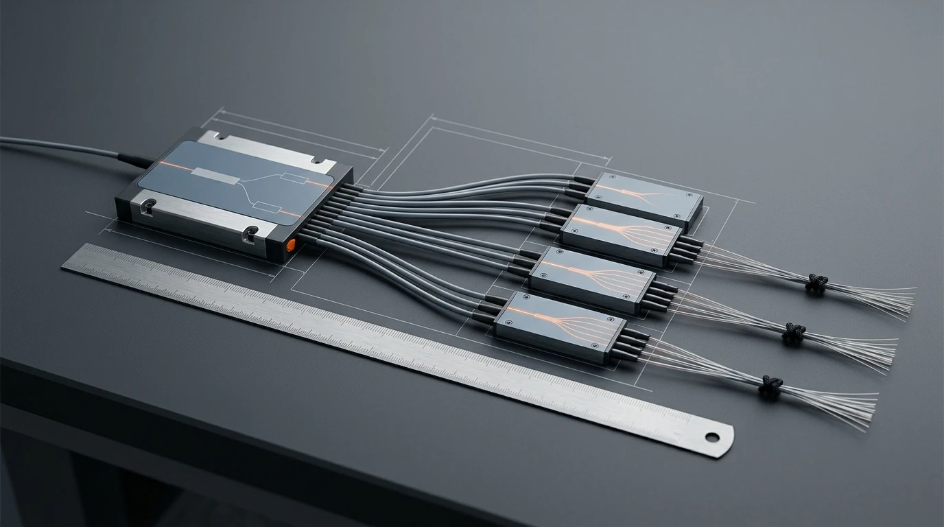
Cascade changes the quantity structure: one module becomes five, and every fan-out adds a connector pair that the loss budget has to pay for.
What Each Line Costs in the Loss Budget
An FTTH BOM has a second column that procurement never sees and operations always feels: decibels. Every passive item on the list either adds loss or is there to protect against it.
Choice on the BOM | Loss it puts in the path | Where it bites |
|---|---|---|
G.652.D single-mode, 1310 nm | 0.35 dB/km uncabled fiber limit, 0.40 dB/km cabled allowance | Long feeder routes; upstream usually sets the worst case |
G.652.D single-mode, 1550 nm | 0.20 to 0.25 dB/km | Downstream looks comfortable while upstream does not |
Fusion splice | 0.10 dB each, 0.15 dB allowed on many specifications | Splice count on a drum-length-constrained route |
Mated connector pair, factory APC | 0.30 dB | Every patch panel, FDB port and ONT connection |
Mated connector pair, field-terminated | 0.50 dB | Field terminations and pre-terminated drops |
1:32 PLC splitter | 16.5 to 17.0 dB maximum | The single largest line in any PON budget |
1:64 PLC splitter | 20.5 dB maximum | Usually pushes a design into a higher optics class |
1:4 + 1:8 cascade | 17.8 dB plus about 0.6 dB of extra connectors | Tempting on feeder cost, expensive in margin |
Bend-insensitive drop cable | 0.75 dB per turn at 10 mm radius for G.657.A1 | Wall entries, skirting and cabinet dressing |
Put those numbers on one route and the design stops being abstract. Worst subscriber path in the reference area: 5 km of feeder at 0.35 dB/km (the datasheet figure for uncabled fiber) is 1.75 dB; 0.4 km of distribution and 55 m of drop add 0.16 dB; twelve closure splices plus two pigtail splices cost 1.40 dB; six mated pairs cost 1.80 dB; the 1:32 splitter costs 17.00 dB. Total, 22.1 dB against a GPON Class B+ budget of 28 dB — a margin of 5.9 dB, of which roughly 3 dB should be held back for repairs, aging and measurement uncertainty. The acceptable loss figures for a fiber link explain how that reserve is usually set.
That leaves about 3 dB of real headroom, and it is spent by exactly two BOM decisions: the splitter ratio and the connector count. A 1:64 in the same position takes the total to 25.6 dB and eats the reserve. Four of those six pairs field-terminated at 0.50 dB instead of 0.30 dB add 0.8 dB on top of that, taking the path to 26.4 dB. Neither change looks like a design decision on a purchase order; both are.
Two loss lines deserve their own attention because they are frequently left off the drawing entirely.
Bend loss on the drop. Drop cable is where fiber is bent by people who are not fiber technicians: around a corner at the wall entry, behind skirting, inside a customer's cabinet. G.657.A1 is specified to keep a single turn on a 10 mm radius inside 0.75 dB at 1550 nm, and G.657.A2 does the same on a 7.5 mm radius within 0.5 dB — against a G.652 fiber whose bend loss at those radii is not something to design around. Prysmian's A1+ data states the 0.75 dB standard limit next to its own 0.50 dB part, which is a useful reminder that the grade is a ceiling, not a performance guarantee. The fiber categories themselves are defined in ITU-T G.657.
Connector count per path. Six mated pairs is a normal FTTH path: OLT patch panel, ODF, cabinet splitter input, FDB port, ONT outlet, ONT. Each pair at 0.30 dB is 1.8 dB; at a field-terminated 0.50 dB it is 3.0 dB. The cheapest way to buy margin on a marginal route is fewer connectors and better ones, not a bigger splitter budget.
Fiber Type, Jacket and Connector Grade: The Lines Written Loosely
Most change orders trace back to a line that was written in six words and meant four different things. These are the four that matter most.
Fiber grade. G.652.D is the default for feeder and distribution: standard single-mode, lowest attenuation, no bend tolerance worth relying on. G.657.A1 belongs in drop cable and in any cable dressed into a tight cabinet; G.657.A2 where the radius really is 7.5 mm or less, typically indoor wall entries and MDU risers. G.657 is backward compatible with G.652 at the splice, so mixing grades is normal — what is not normal is ordering "single-mode" and receiving whichever grade was in stock. Attenuation limits for G.652 cable are set in ITU-T G.652, and the fiber limit and the cabled limit are two different numbers: one example G.652.D datasheet quotes 0.35 dB/km at 1310 nm and 0.21 dB/km at 1550 nm, which is exactly the number to put on the PO.
Jacket and fire rating. Indoor and in-cabinet cable carries a CPR class in Europe and a plenum or riser rating in North America; outdoor cable does not, and the two are not interchangeable at a building entry. If the drop crosses from outside to inside, the BOM needs both constructions or a transition point, not a compromise. The CPR cable class guide sets out which class applies where.
Connector polish. The ODN side of PON overwhelmingly uses SC/APC with an 8-degree angled endface, because angled contacts reflect less light back into the laser. Mixing UPC into an APC link is the classic field error: it mates, it passes a quick continuity check, and it delivers a reflective connection with poor return loss. Write "SC/APC, 8°, green housing" and check the housings on arrival — the APC versus UPC comparison covers the measurement consequence.
Connector and adapter grade. Specify maximum insertion loss per mated pair, minimum return loss, and the endface acceptance criterion by standard rather than by adjective. "Low loss" is not a specification; "≤0.30 dB maximum insertion loss, ≥60 dB return loss, endface pass per IEC 61300-3-35" is.
Spares and Attrition: A Policy per Item Class
A flat 10 percent across an entire FTTH BOM is the most common spare policy and the least useful one. Cable is wasted by cutting, not by breakage. Splitters are not consumed at all — they are damaged, mis-shipped, or needed because the design changed. Connectors are consumed by handling. One percentage cannot cover four different failure modes.
Item class | Allowance | What the allowance is actually for |
|---|---|---|
Cable on drums | +5% per route segment | Reserve loops at closures and cabinets, as-built deviation |
Drop cable | +8% of cut length | Cut waste per drop, re-pulls, wrong-length drops |
Splitters | +2 units per ratio | Design change, handling damage, one spare per cabinet |
FDB and closures | +2 to +3 units, +15% ports | Breakage in transit, one spare box per area |
Pigtails and adapters | +5% | Splice rework, damaged ferrules, missing adapters |
ONT / power supply | +5% | DOA units and on-site damage |
Patch cords | +10% | Handling damage; the item most often borrowed and lost |
Field-install connectors | +10% | Termination failures and re-terminations |
Splice protectors | +15% | Sleeves split on insertion and are never reused |
Clamps, brackets, wall entries | +10% | Route changes during construction |
Cleaning consumables, labels | +25% | Consumed per port, per splice, per handover |
Two rules keep this honest. First, drum waste is a design error, not a spare allowance: if a 500 m drum is being cut for a 380 m run, the fix is a drum-length schedule per segment, not a bigger percentage. Second, the allowance is per item class, not per purchase order — a 15 percent allowance on splice protectors costs a few dollars, while a 15 percent allowance on 48-fiber cable is money buried in a warehouse.
Incoming Inspection: What to Measure Before It Goes in the Ground
Nothing on this list is hard to check, and almost none of it is checked. A drum that arrives 40 m short, a splitter whose worst port is 1.5 dB worse than the average, a box of adapters with the wrong sleeve — each is trivial to find on the loading dock and expensive to find after installation.
Check | Method | Acceptance | Coverage |
|---|---|---|---|
Drum length | Counter reading plus tape on the outer end | Within the tolerance stated on the PO | Every drum |
Sheath and print | Visual | Legible print, meter marks, no sheath damage or crush | Every drum |
Cable attenuation | OTDR from both ends, or a launch-receive test | At or below the datasheet figure at 1310 and 1550 nm | Every feeder drum, sample of drop drums |
Connector endface | Video scope to IEC 61300-3-35 | Pass in the zone criteria, no scratches in the core zone | 100% of pre-terminated drops |
Patch cord insertion and return loss | OLTS or source and meter | ≤0.30 dB insertion loss, ≥60 dB return loss on APC | Sample per batch against an agreed AQL |
Splitter per-port loss | Certificate review, plus retest of a sample | Every port at or below the stated maximum, uniformity within spec | 100% of certificates, 5% retest |
Adapter and housing | Visual and gauge | Correct polish keying, ceramic sleeve present, no damage | Sample per carton |
Closure sealing | Factory test evidence | IP68 test report for the model supplied | Document review |
Splice protectors | Dimensional check | Correct sleeve length for the fiber count, no deformation | Sample per bag |
Three practical notes. Stop the drum at the gate, not at the trench — a length discrepancy found after the cable is pulled is a claim, not a replacement. Read the splitter certificate per port, not per unit: the average is fine on almost every module, and the worst port is what your budget has to survive. And name an AQL if you are going to sample — ISO 2859-1 is the standard most quality teams use, and a stated inspection level turns "we checked a few" into a defensible record.

The three checks that catch most bad deliveries: endface under a scope, insertion and return loss on a meter, and a length reading against the drum marking.
The Omission That Stalls Handover: The Acceptance Test Kit
Ask what delays an FTTH project at the end and the answer is rarely cable. It is that nobody can prove the network passes, because the equipment needed to prove it was never on the BOM.
The FTTH equipment list for handover is longer than most BOMs admit. Acceptance on a PON needs an optical loss test set or a calibrated source and power meter, reference test cords with the right connector type and known-good loss, a video inspection scope with adapters for every connector family in the build, lint-free wipes and cleaning fluid, a visual fault locator, and — if the contract calls for tier 2 — an OTDR with launch and receive cables long enough for the split ratio. That last item is where projects stall: an OTDR trace through a 1:32 splitter without a suitable launch cable shows a large step and a dead zone, not a splice.
The FOA's guidance on inspecting and cleaning connectors makes the operational point better than any specification: a dirty connector contaminates the clean one it mates with, and a protective cap is not a clean cap. Which means the cleaning consumables are not a consumable line at all — they are part of the acceptance equipment, and they have to be on site before the first drop is terminated, not ordered when the first link fails.
Three more omissions that surface at the same late stage:
- Pigtails and adapters for ports you have already counted. The splitter count is right, the FDB count is right, and there is no line for the 2,150 pigtails and the 2,150 adapters that turn those ports into connections. It is the most common arithmetic gap in the whole document, because the ports and the terminations live in different sections of the design.
- The as-built record set. Port maps, splitter serials, splice records and measured per-port loss are deliverables, and they need labels and a document format in the BOM, not a promise to produce them later.
- Customer-side hardware nobody owns. ONT, power supply, internal outlet and the patch cord to the ONT are sometimes the operator's, sometimes the contractor's, and occasionally the customer's. If the BOM does not say which, it will be discovered at the first installation.
What to Write on the RFQ Line
The BOM tells you what to buy; the RFQ line decides what arrives. Eleven fields turn a line item into a specification a supplier can be held to.
Field | What to write | Why it matters |
|---|---|---|
Fiber type and grade | G.652.D for feeder and distribution, G.657.A1 or A2 for drop, with the ITU-T reference | Prevents substitution with whichever grade is in stock |
Attenuation | Maximum dB/km at 1310 and 1550 nm | The standard's limit is looser than a good datasheet |
Cable construction | Fiber count, loose tube or flat, strength member, jacket material, CPR class | Determines whether it can be installed on the route at all |
Connector | SC/APC 8°, maximum insertion loss, minimum return loss, endface standard | The two numbers that decide the link budget |
Adapter | Type, sleeve material, maximum insertion loss | Cheap part, measurable loss |
Splitter | Ratio, maximum loss per port at each PON wavelength, uniformity, return loss | The largest single loss line on the BOM |
Closure or FDB | Capacity, IP rating, cable diameter range, tray count, splitter accommodation | Fit, not performance — and fit is what stops installation |
ODF | Port count, loaded or empty, adapter type, frame height | "48-fiber ODF" is ambiguous without loaded or empty |
Length and packing | Drum lengths per route segment, length tolerance, packing list per segment | Turns a cable order into an installable one |
Traceability | Serial numbers on drums, closures and splitters, linked to route segment | The only way to investigate a fault in year three |
Test evidence | Per-port splitter report, patch cord IL and RL, endface pass record, material certificates | Acceptance evidence you can file, not a verbal assurance |
Add the optics class while you are at it. ITU-T G.984.2 defines the GPON physical-media classes your link has to satisfy, and ITU-T G.9807.1 does the same for XGS-PON, where 1:64 is the usual ratio and a 1:8 + 1:8 cascade is how most planners reach it without pulling more feeder fiber. If the BOM is silent on class, procurement will substitute the cheaper SFP, and the design margin disappears without a single passive part changing.
Where TTI Fiber Fits
Most of this document is arithmetic that any careful planner can run without a supplier. The part a supplier affects is the guaranteed numbers: maximum loss per splitter port, uniformity across ports, connector insertion and return loss, and whether the test report that comes with the delivery actually states the measurement method. TTI Fiber manufactures GPON splitter modules and patch cords in the ranges these BOMs call for, and the useful conversation at quotation stage is not price per unit — it is which maximum each line will be held to.
FAQ
How many splitters do I need for 1,000 homes?
Size on homes passed, not on subscribers: 1,000 ÷ 32 = 31.25, rounded up to 32, plus two spares, so 34 for a 1:32 design. At 60 percent take-up only 19 of those splitters have live subscribers in year two, but all 32 are installed, because a home passed without a splitter port cannot be activated without a cabinet visit and a splice.
Is G.657.A2 required for drop cable?
Not required, but it is the safer default where the route includes tight wall entries or MDU risers. G.657.A1 holds 0.75 dB per turn at a 10 mm radius; A2 holds 0.5 dB at 7.5 mm. If every drop terminates on an outside wall with a generous loop, A1 is sufficient and cheaper. If drops run behind skirting or through tight conduit, the extra tolerance is worth more than the price difference.
What spare percentage should a BOM carry?
None as a single number. Cable takes about 5 percent for route reserve plus a drum-length plan, drop cable about 8 percent for cut waste, splitters two units per ratio, splice protectors 15 percent, and cleaning consumables 25 percent. The percentages differ because the failure modes differ — and drum waste should be designed out, not covered by an allowance.
Which test reports should I demand with the delivery?
Per-port insertion loss for every splitter, at each PON wavelength, with the measurement method named; insertion and return loss for patch cords and pigtails; endface inspection results to IEC 61300-3-35; and environmental test evidence for closures, typically an IP68 report for the model supplied. Reports that state "typical" values without a maximum are not acceptance evidence.