Fiber Optic Fast Connector Termination
When to Use a Fast Connector in FTTR Work (and When to Fuse Instead)
FTTR deployments push a fiber drop from a central ONT or distribution point to an optical terminal in each room. That means many low-fiber-count terminations at the customer premises, often on existing homes where the drop cable is fished through walls and terminated into small wall panels. This is exactly the environment fast connectors were designed for: they need no power, no fusion splicer, and no curing time, and they tolerate being installed on a ladder or in a cramped riser.
Use a fast connector when the job is a handful of terminations at the subscriber end — FTTR room drops, FTTH home installs, emergency repairs, or patch panel re-terminations. Choose fusion splicing instead when you are terminating high-fiber-count cables (distribution points, ODFs, splice closures), when the link budget is so tight that every tenth of a decibel matters, or when a splicer and qualified operator are already on site. There is a real trade-off: a fusion splice inside a splice-on connector adds far less loss than the mechanical splice inside a pre-polished fast connector, and the Fiber Optic Association's reference on pre-polished/splice connectors puts a well-made prepolished termination at roughly 0.5–0.7 dB total loss at best. For FTTR's short indoor links that margin is usually acceptable; for long-reach PON spans it may not be.
The rest of this guide assumes the first case: you are terminating FTTR drop cables on site. If you are still deciding between FTTR and mesh Wi-Fi, or want the bigger picture first, our FTTR (Fiber to the Room) hub and the FTTR basics explainer are the right starting points.
Choose the Right Fast Connector: SC vs LC, UPC vs APC
The three decisions that matter when you order fast connectors are interface type, polish type, and cable-size variant. Get these wrong and no amount of careful termination will save you.
Interface: SC is the FTTR default. The SC connector dominates FTTH and FTTR because it is rugged, snap-lock, and specified for high-density patch panels and wall outlets. LC is the choice when space is tight — duplex LC in an optical terminal or transceiver side — and ST still appears in legacy plant. For a full comparison of common fiber optic connector types, see our connector primer. In practice, an FTTR room terminal almost always expects SC, so stock SC fast connectors for the bulk of the job.
Polish: APC for PON, UPC for most everything else. GPON and XGS-PON use a single fiber for both directions, and reflections from a UPC end face can interfere with the upstream laser, so PON deployments use SC/APC (green housing, 8° angled polish). UPC (blue) is the norm for other singlemode links, and never mix the two in one link — an APC mated to a UPC ferrule is a guaranteed high-loss, high-reflection connection. Our APC vs UPC guide covers the physics and the color codes. The AFL FASTConnect specification shows what the polish choice is worth in numbers: singlemode UPC averages 0.2 dB insertion loss, while APC averages 0.3 dB, and APC return loss averages −55 dB versus −50 dB for UPC.
Cable-size variant: match the connector to the drop cable. Fast connectors come in versions for 250 µm and 900 µm coated fiber, for 2 mm and 3 mm round cordage, and for the 2.0 × 3.0 mm flat drop cable that FTTH and FTTR installs use most. Using a 900 µm connector on a flat drop cable means improvising with adapters, which is where terminations start failing before you even cleave. If you are specifying cable and connectors together, TTI Fiber's FTTH drop cable range and pre-polished fiber optic connector range are designed to match. Order spares: with practice, first-attempt yield should be high, but every installer gets a bad cleave occasionally, and a spare connector beats a second site visit.
What You Need: Connector, Tool Kit, and Cable Prep
A fast connector kit is small enough to live in a belt pouch, but every item has a job:
- Fast connectors of the correct interface, polish, and cable size, plus spares.
- Fiber strippers sized for your cable — one for the 2.0 × 3.0 mm jacket and strength members, one for the 250/900 µm coating.
- A precision cleaver. The FOA is blunt about this: pre-polished connectors "require a very precise cleave from a top quality cleaver," and technicians who hit around 0.5 dB total loss are using the same quality of cleaver you would pair with a fusion splicer. The cleaver that ships in a cheap kit is often the first thing to upgrade.
- Lint-free wipes and reagent-grade 99% isopropyl alcohol. Per the FOA's cleaning guidance, never use cotton swabs or cloth — they leave threads — and never use ordinary isopropyl, which can leave residue that attracts more dirt.
- A VFI (visual fault locator), the red-laser pen that costs a few dollars and pays for itself on the first ambiguous splice.
- An inspection microscope (100–400×) if you do production-scale work; see the inspection section below.
- A light source and power meter if you are responsible for proving the link, not just making the connector.
Cable prep starts before the first strip. Inspect the drop cable run for kinks, crushed sections, or water ingress — a damaged cable will fail your termination and you will re-terminate for nothing. Then strip back the jacket and strength members far enough to expose the coated fiber, and remove the coating to expose bare fiber for the length your connector specifies. Wipe the bare fiber once with the alcohol pad before you cleave. The fiber you insert into the connector is the fiber you will live with; the FOA notes that a typical airborne dust particle is nearly the size of a singlemode core, and dirt trapped between the two fiber ends is a direct insertion-loss and reflection penalty.
How to Terminate a Fast Connector: Step by Step
The sequence below matches the mechanical-splice pre-polished connectors used in FTTR work (SC/APC on flat drop cable). The principle is identical across brands — strip, clean, cleave, insert, lock, boot — but follow your connector's own instructions where they differ, especially for cleave length.
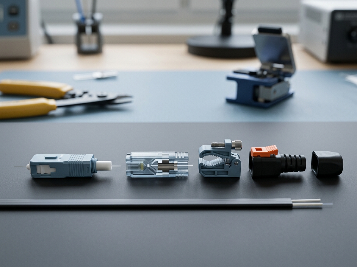
Anatomy of a mechanical-splice fast connector: the factory-polished ferrule and stub on the left, the splice housing that grips your cleaved fiber in the middle, and the boot that provides strain relief on the right.
Step 1 — Strip the cable. Remove the outer jacket and strength members with the correct stripper, then strip the coating to expose bare fiber. Leave the bare fiber length the connector specifies — most SC mechanical-splice fast connectors want roughly 10–15 mm of bare fiber, and the connector's gauge or instruction sheet is the authority. Expected result: a smooth, undamaged coating edge with no nicks in the bare fiber.
Step 2 — Clean the fiber. Wipe the bare fiber with a lint-free wipe and 99% isopropyl alcohol, then dry it with a dry section of the pad. Expected result: the fiber looks uniformly clean under light; if you see specks or residue, repeat the wipe — do not proceed.
Step 3 — Cleave the fiber. Position the fiber in the cleaver so the cleave lands at the exact length your connector requires (next section covers this in detail). Expected result: one clean, perpendicular break with no lip, chip, or feather. If the end looks anything but clean, re-cleave before you commit.
Step 4 — Insert the fiber into the connector. Open the connector's clamp or crimp mechanism, slide the fiber through the rear opening, and advance it until it seats against the internal factory-polished stub. On most designs you can see the fiber reach the splice point through a viewing window, or feel it stop. Expected result: the fiber tip sits flush against the stub with no gap visible in the window.
Step 5 — Lock the mechanism. Push down the cover or close the crimp per the design, keeping gentle tension on the fiber while you do it. The FOA stresses holding the fiber under tension during crimping "to make sure the two fiber ends in the internal splice stay in contact." Expected result: the fiber is clamped and cannot slide back when you tug lightly.
Step 6 — Secure the boot. Slide the boot up over the connector body and lock it over the cable jacket. This is the strain relief that keeps the splice from flexing every time the drop cable moves. Expected result: the cable, boot, and connector form one rigid assembly; bending the cable near the connector does not move the fiber inside.
Step 7 — Verify with the VFI. Shine the visual fault locator into the connector's far end (or the fiber's far end) and watch the splice area through the translucent connector body. A good splice shows minimal red glow at the splice point; a bright hotspot means the fiber ends are not in contact. The FOA recommends exactly this trick — "confirm the splice is good when the red light is minimized." Expected result: dim, even light through the body, no bright spot. Do not mate the connector to anything yet; the ferrule end face gets inspected and cleaned before it touches a port.
Cleaving: The Step That Decides Insertion Loss
Everything downstream of the cleave is mechanics — the connector's internal splice aligns your fiber to the stub and index-matching gel fills the interface. But the internal splice can only be as good as the end you present to it. A cleave with a lip, a chip, or an angle leaves an air gap or a misaligned joint at the splice point, which shows up directly as insertion loss and reflection. This is why the FOA calls the cleave the make-or-break step for pre-polished connectors and why "the good kits with quality cleavers" cost more.
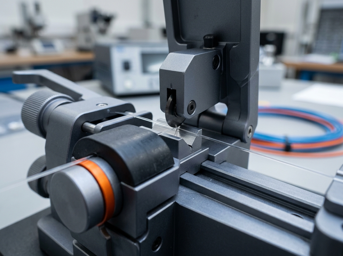
The cleave is a controlled break: one clean, perpendicular end with no lip or chip is the difference between a 0.3 dB and a 0.7 dB termination.
Three cleaving rules carry most of the value:
Cleave to the connector's specified length, not a habit. Each connector design expects a specific bare-fiber length so the tip ends exactly at the internal splice. Too short and the fiber never reaches the stub; too long and it pushes past the splice point or buckles. Use the gauge on the connector's instruction sheet — and when switching between 900 µm and flat-drop versions of the same connector, re-check the length; they are often different.
Use a quality cleaver and maintain it. A fusion-splice-grade cleaver produces consistent, low-angle cleaves; a dull blade produces chips. Rotate or advance the cleaver blade on the manufacturer's schedule, and clean the blade and anvil regularly — dust on the anvil is a chip on your fiber.
Re-cleave when in doubt. A bad cleave costs one connector if you commit to it, or ten seconds if you catch it first. Look at the end before insertion: no feather, no chip, no angled mirror surface. Some connectors are designed to allow the fiber to be reinserted — the AFL FASTConnect, for example, states the fiber can be reinserted up to three times — but treat that as a rescue path, not a routine. The VFI check from Step 7 is your second opinion: if the red light is bright at the splice, the cleave was wrong, and re-terminating with a fresh connector is cheaper than testing a bad one.
Inspect Every Termination: VFI and Microscope Checks
A termination is not finished when the boot snaps on. The FOA's inspection reference is blunt about the stakes: dirt on a ferrule end face is typically silica-based and hard enough to scratch the fiber when two spring-loaded ferrules are mated, and a dirty connector transfers its contamination to whatever it touches. That means the connector you are about to plug into a room terminal can damage the terminal's port, not just degrade its own performance.
Two inspection layers:
VFI first, on every connector. The visual fault locator checks the internal splice (Step 7). It also catches cracked fibers and gross termination errors in seconds. It cannot see the ferrule end face, which is why the microscope comes next.
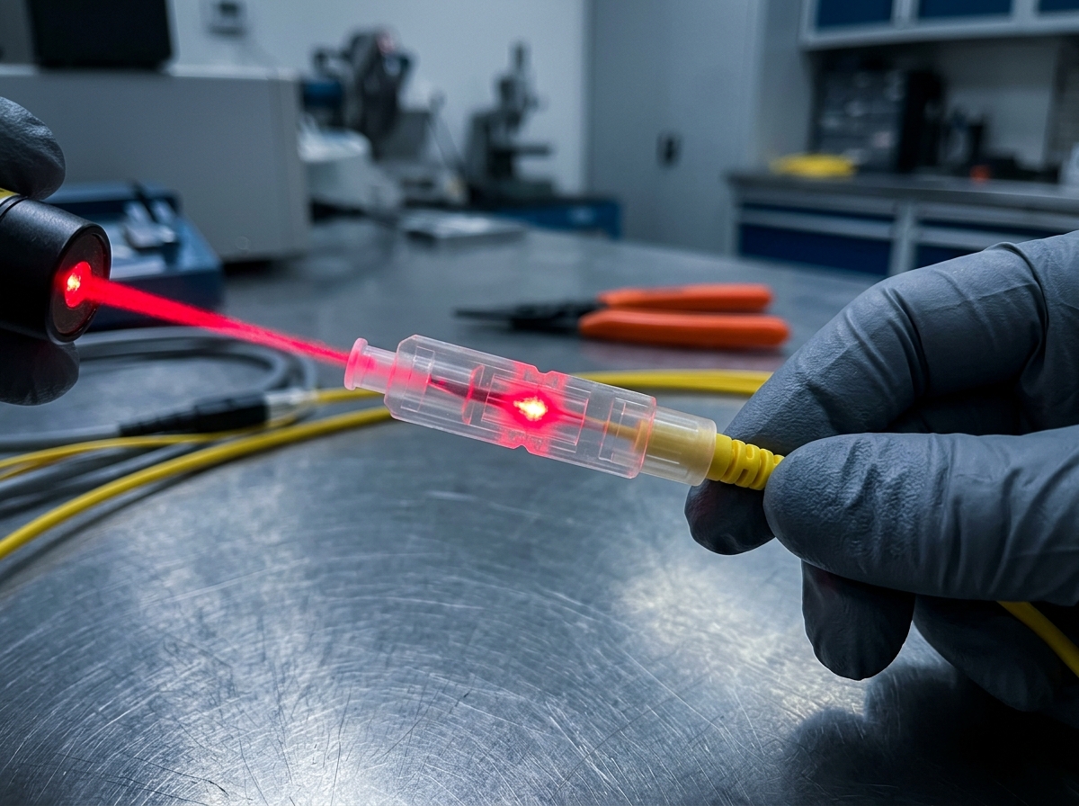
A bright red hotspot at the splice point means the fiber ends are not in contact; dim, even glow means the splice is good.
Microscope on anything that will be mated. A fiber inspection microscope at 100–400× shows the ferrule end face directly: dust, oil, scratches, chips, and the edge of the fiber core. Inspect after termination and again right before mating, because a connector exposed to air for an hour accumulates a new film of dust. If the end face is not clean, wet-clean with the alcohol pad, dry with a lint-free wipe, and re-inspect — and never assume a protective cap keeps a connector clean, since caps pick up mold release and shop dust on their own. Per the FOA cleaning guide, clean connectors before every mating, "whether for testing or making network connections," and clean your test reference cables before every test too.
Seven Common Mistakes That Fail Fast Connector Terminations
Most field failures are not exotic. They are the same handful of errors repeated, and each one has a cheap fix:
Mistake | Symptom | Fix |
|---|---|---|
Skipping the alcohol wipe | High loss from dust trapped in the internal splice | Wipe bare fiber with 99% IPA lint-free pad before cleaving |
Cleaving to the wrong length | Fiber bottoms out or never reaches the stub; VFI shows a bright gap | Measure against the connector's gauge every time |
Committing to a chipped cleave | Elevated loss and reflection at the splice point | Inspect the cleave end; re-cleave before inserting |
Inserting the fiber at an angle | Fiber buckles or misses the splice channel | Keep the fiber straight and aligned while advancing it |
Releasing tension before locking | Fiber retracts, leaving an air gap at the splice | Hold light tension on the fiber while closing the clamp |
Forgetting the boot until after locking | No strain relief; the fiber breaks at the connector under cable movement | Slide the boot onto the cable first, always |
Mating before inspection | Contamination transfers to ports; ferrule gets scratched | VFI + microscope check and clean before mating |
The pattern to notice: every row traces back to preparation or to rushing the last two steps. If you find yourself re-terminating more than one connector in ten, slow the cleave step and check your tooling.
"The secret to lowering costs is getting high yield of good connectors and that depends on having the right tools and training – and practice." — The Fiber Optic Association, on pre-polished/splice connectors
Test the Link, Then Decide: Pass, Fix, or Re-terminate
The last word on any termination belongs to a loss measurement, not a visual check. A light source at one end and a power meter at the other measures the real link loss, including every connector, splice, and bend in the path. The standardized way to isolate connector loss is the TIA FOTP-34 connector and splice loss test method, which measures the power change when a mated connector pair is inserted into a reference cable — and note that a connector on its own has no loss; what you measure is always a mated pair.
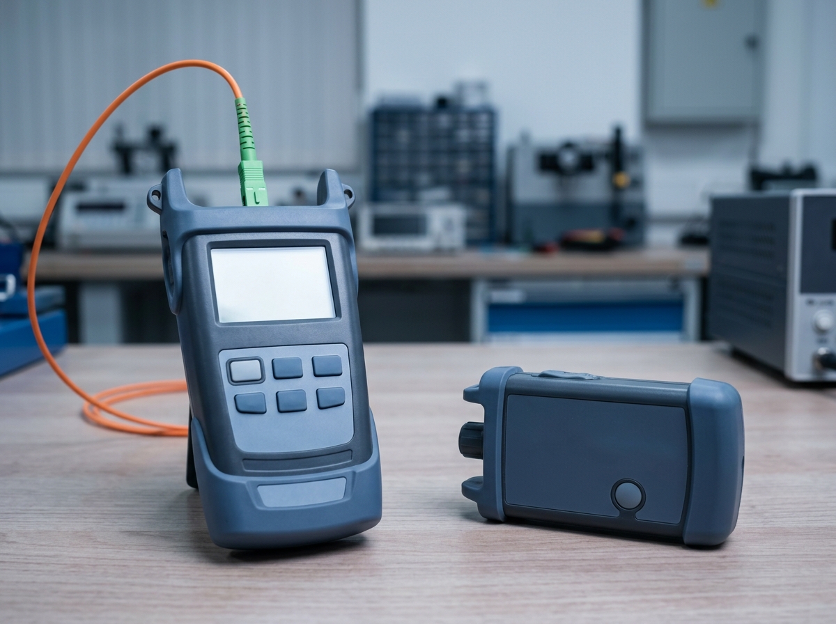
End-to-end loss testing: launch a known power from the light source, read the received power at the meter, and compare the difference against your link budget.
Interpreting the numbers:
- Per-connector expectation. A well-terminated pre-polished fast connector lands around 0.5 dB total, and the FOA notes technicians routinely beat the TIA-568 requirement of 0.75 dB or less with a quality cleaver. Manufacturer specs are similar: AFL rates its FASTConnect at 0.2 dB average (0.5 dB max) for singlemode UPC and 0.3 dB average (0.5 dB max) for APC, and Fujikura claims under 0.5 dB for its FAST series. If your end-to-end measurement shows more than roughly 0.75 dB per fast connector termination, something in that termination is wrong.
- Link budget. Sum every connector, splice, and the cable attenuation to check against the PON link budget. For context on what counts as normal loss across a whole path, see what constitutes a good dB loss in fiber optics.
When a test fails, work the fix ladder in order: re-clean first — contamination is the most common cause of high loss, and it costs nothing; re-seat next — if the connector permits reinsertion, unlock, re-cleave cleanly, and try again; re-terminate last — with a fresh connector, on a fresh cleave, and verify with the VFI before you measure again. Do not be tempted to leave a marginal connector in place "because it passes at the ONT." Reflections that are invisible to a power meter can still disturb a PON upstream laser, which is precisely why PON plant uses APC end faces; the FOTP-34 reference notes a non-contacting air-gap connection reflects about 4% per glass-air interface — roughly 0.3 dB of that connector's loss — and in high-bit-rate singlemode systems that reflection is a source of bit-error problems.
Field Termination Checklist (and Where to Source Parts)
Print this and keep it in the kit bag:
- Connector type matches cable type (flat drop vs 900 µm), interface (SC), and polish (APC for PON).
- Boot and strain relief are on the cable before you start.
- Bare fiber stripped to the connector's specified length, coating edge smooth.
- Fiber wiped with 99% IPA, dried, inspected.
- Cleave clean and perpendicular; re-cleave if not.
- Fiber seated against the stub (visible in the viewing window).
- Clamp locked with light tension on the fiber.
- Boot secured; cable movement does not flex the splice.
- VFI: no bright hotspot at the splice.
- End face cleaned, inspected, capped until mating.
- Loss measured and recorded against the link budget.
When you are sourcing connectors, cleavers, and FTTR drop cable for a deployment, TTI Fiber's fiber optic connector range and FTTH drop cable range cover the SC/APC fast connector and flat drop combinations used in FTTR installs, with termination kits available through the same product line. And before you run a production job, spend an afternoon on scrap cable — the FOA calls training on the exact termination process "absolutely mandatory," and the yield difference between a practiced hand and a first-timer is exactly what makes fast connectors either the cheapest termination method in the industry or the most expensive one.