Optical Fiber Patch Cord Selection Guide
Most patch cords are bought the same way: someone re-orders the part number from the last project, or picks the cheapest LC duplex cord on a distributor's shelf and assumes the rest is detail. Then the cord arrives and one of four things is wrong — the connector will not seat in the adapter, the polish will not mate with the far end, the jacket class fails the inspector's walk-through, or the length is 8 cm short in a route that has no slack.
None of those are manufacturing defects. They are specification gaps, and they are cheap to close at the quotation stage and expensive to close on site.
This guide treats an optical fiber patch cord as what it actually is: a six-variable assembly. Work the variables in the order below and each one eliminates whole families of options before you spend time on the next. That is the difference between choosing a cord and guessing at one.
What an Optical Fiber Patch Cord Is — and the Six Variables Behind Every SKU
An optical fiber patch cord — usually just called a fiber patch cord, and often sold as a fiber optic patch cable — is a short, factory-terminated fiber assembly with a connector on each end: a connector, a length of jacketed cable, and a strain-relief boot that keeps the fiber from bending at the ferrule. It exists to move light between two ports that were never designed to be permanently joined — an adapter panel and a switch, a cassette and a transceiver, an OLT and an ODF.
The definition is trivial. The specification is not, because "LC duplex single-mode 3 m" describes a cord the same way "sedan" describes a car: mode, channel count, connector family, polish, jacket rating and length all sit underneath that phrase, and each one can be wrong independently. The table in the next section lists them in the order that eliminates options fastest.
If you are new to the physics behind these choices, the fiber optics fundamentals hub covers how light propagates, what attenuation is, and why a connector matters at all. This article assumes you know roughly what you need and are deciding what to specify.
Fiber Patch Cord Types, in the Order You Decide Them
Most guides to types of fiber patch cords sort by connector family, which is the one axis a buyer usually does not get to choose. Sorting the other way — by the constraint that eliminates the most options first — leaves far fewer fiber patch cord types on the table by the time you reach the part number. Answer the six questions below in order. Each row narrows the next: mode decides which connector colors and polish options exist, channel count decides whether you are buying a duplex assembly or a multi-fiber harness, and jacket class decides whether a cheaper cord is even legal in the space you are cabling.
Axis | Options | What decides it |
|---|---|---|
Mode | OS2 single-mode; OM1–OM5 multimode | Transceiver type and the reach you must cover |
Channel count | Simplex, duplex, 8/12/16/24-fiber MPO | Port pairing and the optics lane count |
Connector | LC, SC, ST, FC, MPO/MTP | What the adapter, panel or transceiver is built for |
Polish | PC, UPC, APC | Whether the link carries RF video, DWDM or PON, and what the far end already uses |
Jacket | LSZH, PVC, OFNR, OFNP, CPR class | The space the cable runs through and the local code |
Length | Stock 1/2/3/5/10 m or custom | Route geometry, slack, and tolerance on the drawing |
Two of these six are effectively irreversible once the order is placed: polish (because the end face is lapped at the factory) and jacket class (because it is a material and test decision, not a label). The other four can be re-ordered, at a price. Spend your checking time accordingly.
Axis 1: Single-Mode or Multimode
This is the first fork because it changes the fiber core, the jacket color, the transceiver and the reach all at once.
Single-mode fiber carries one propagation path in a core of about 9 µm inside a 125 µm cladding, written 9/125 µm. Its attenuation is low enough that standard 10G optics reach 10 km, and 100G reaches the same distance with four-wavelength optics. The ITU-T G.652 recommendation is the baseline specification most single-mode cord fiber is built to. A single mode fiber patch cord is yellow.
Multimode fiber has a 50 µm or 62.5 µm core that carries many paths at once. It is cheaper to light up — short-reach optics cost a fraction of single-mode optics — but modal dispersion limits how far the light travels before the pulses smear. The ITU-T G.651 recommendation defines the 50/125 µm graded-index family that OM3, OM4 and OM5 are built on. Multimode fiber patch cords are aqua, violet, lime or orange depending on grade.
Grade | Core | Jacket color | Working reach | Where it belongs |
|---|---|---|---|---|
OS2 | 9/125 µm | Yellow | 10 km at 10G; 10 km at 100G with LR4 | Campus backbone, FTTH, metro, anything leaving the building |
OM3 | 50/125 µm | Aqua | 300 m at 10G; 100 m at 40G; 70 m at 100G | Legacy data-center links, short backbone |
OM4 | 50/125 µm | Aqua or violet | 400 m at 10G; 150 m at 40G; 100 m at 100G | Default choice for 10G/40G/100G inside a building |
OM5 | 50/125 µm wideband | Lime | 100 m at 100G with SR4; 150 m with SWDM4 | New builds where SWDM optics are planned |
OM1/OM2 | 62.5/125 or 50/125 µm | Orange | 33–82 m at 10G | Existing plants only; not a new-build choice |
A note on that last row: OM1 and OM2 share a jacket color but not a capability. OM1's 62.5 µm core carries far less modal bandwidth than OM2's 50 µm core, which is why a 10G link over OM1 tops out around 33 m while the same optics reach 82 m on OM2. If you are replacing an orange plant, count what is actually installed before ordering orange again.
Two practical notes. First, the color code is not decoration — it is the field check that stops a single-mode cord being pushed into a multimode port. The assignment of colors to fiber positions inside a cable comes from the TIA-598 color code, which is worth knowing if you build or trace harnesses. Second, do not mix grades on one link: an OM3 cord between OM4 panels drops the whole channel to the OM3 distance limit. If you are still weighing the two families, our single-mode vs multimode comparison works through the cost crossover.
Axis 2: Simplex, Duplex or Multi-Fiber
Channel count is decided by how the optics use the fiber, not by how many ports are free.
A simplex cord carries one fiber, so it can only work where transmission happens in one direction per fiber — or where a single strand is split for transmit and receive by wavelength. Bidirectional (BiDi) optics do exactly that: one strand, two wavelengths, one direction each. A simplex cord is the right purchase for a BiDi link and the wrong one for a conventional 10G link, which needs a pair.
A duplex cord carries two fibers in a figure-eight or zip construction, one for transmit and one for receive. It is the default for 10G through 100G duplex optics and for nearly all enterprise and FTTH patching — in practice the simplex vs duplex fiber decision is made by the transceiver, not by the rack. Most installers specify duplex without thinking about it, and most of the time that is correct.
A multi-fiber cord carries 8, 12, 16 or 24 fibers in a single MPO/MTP ferrule. It exists because parallel optics use lanes: 40G uses four lanes, 100G uses four, 400G uses eight. Twelve-fiber MPO is the workhorse; 24-fiber MPO halves the trunk count in dense panels. Multi-fiber is also where polarity stops being a detail and becomes a design decision — see MPO polarity types A, B and C before you order a trunk.
A hybrid or conversion cord — an SC/APC to LC/APC assembly, or an MPO-to-LC breakout — exists to join two connector families without an adapter, and it is the cheapest place to introduce a polish mismatch if the two ends were specified separately. One cost trap lives here too: buying duplex cords to feed a multi-fiber panel through breakouts is legitimate, but each breakout adds two mated pairs to the channel. At 0.3 dB per mated pair, two breakouts — four mated pairs in all — spend 1.2 dB of a channel budget that is under 2 dB on a 100GBASE-SR4 multimode link.
Axis 3: Connector Family
Connector choice is usually forced by the hardware — adapters, cassettes and transceiver cages are built for one family. The decision only feels open when you are buying a new panel, and then density and field behavior decide it.
Connector | Ferrule | Coupling | Typical density | Where it survives |
|---|---|---|---|---|
LC | 1.25 mm | Push-pull latch, small form factor | Highest per U | Data centers, SFP/QSFP ports, patch panels |
SC | 2.5 mm | Square push-pull | Medium | FTTH, OLT/ONT ports, ODF, telecom rooms |
ST | 2.5 mm | Bayonet twist | Low | Legacy multimode plants, industrial cabinets |
FC | 2.5 mm | Threaded nut | Low | Test equipment, OSP, high-vibration environments |
MPO/MTP | MT ferrule, 8–24 fibers | Push-pull with guide pins | Highest per connector | 40G/100G/400G trunks, cassettes, harnesses |
Density settles the LC vs SC choice more often than preference does. The physical reason LC dominates new builds is the 1.25 mm ceramic ferrule. Halving the ferrule diameter cuts the end-face area to a quarter, but housings, latches and panel tolerance spend about half of that gain, so the density you can actually buy is roughly twice the SC's: a board or panel that takes 24 duplex LC ports takes only 12 duplex SC ports in the same space. The transceiver makers standardized on the LC, and that settled the argument. SC remains the default at the access layer because it is easier to handle with gloves and easier to clean in a street cabinet. ST and FC persist in plants that were built around them; a new project rarely chooses either.
MTP is not a different connector from MPO in the way SC is different from LC — it is a refined MPO (a US Conec design) with a removable guide-pin housing and tighter spring tolerances. In practice the two mate, and the differences that matter are pin gender (male/female) and polarity, not the name on the housing. If you need the full family comparison, our guide to fiber optic connector types covers the mechanical detail; the FOA fiber optic connector identifier catalogs each interface by ferrule size and latch mechanism.
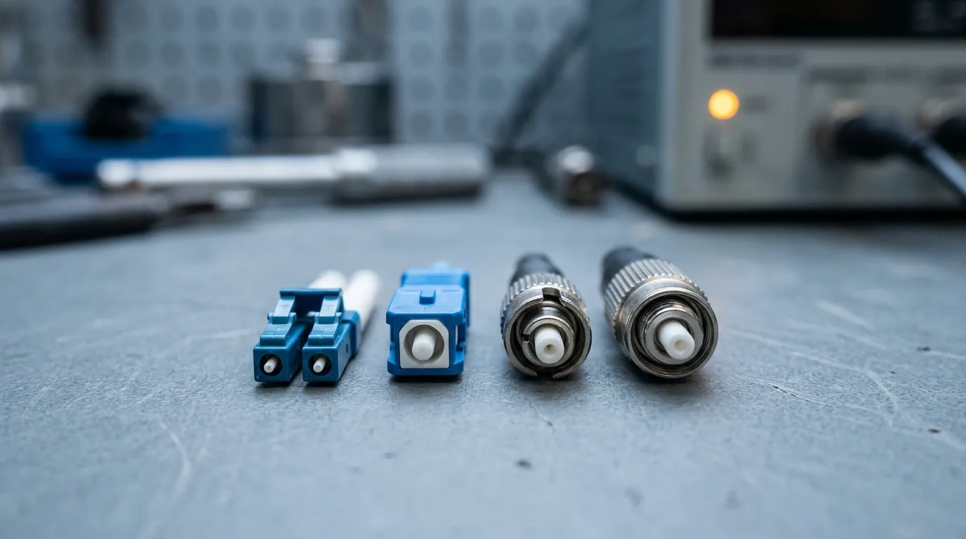
What the photo shows is the real selection criterion: ferrule size and latch mechanism, not brand. Left to right, the blue duplex LC pair is what a switch port takes, the square SC body is what an ODF takes, and the two metal-bodied 2.5 mm connectors are the older ST and FC styles that still sit in legacy plant and on test benches.
Connector performance is standardized rather than brand-dependent: a cord built to the grade tests to the same limits at the far end, whichever factory built it. The cabling standard that sets those grades is the ANSI/TIA-568 family, whose fiber part defines the connector and channel limits.
Axis 4: UPC or APC
This is the decision that cannot be fixed in the field. PC, UPC and APC are three end-face geometries, and the geometry is lapped into the ferrule at the factory. You cannot convert one to another by cleaning it harder.
- PC (physical contact) — the original domed polish. Still common on multimode.
- UPC (ultra physical contact) — a tighter dome with better return loss, the default for single-mode Ethernet. Blue housing on single-mode.
- APC (angled physical contact) — the end face is ground at an 8° angle so the reflection is bent away from the core instead of traveling back into the laser. Green housing. Return loss improves by roughly an order of magnitude, which is why PON, RF-over-glass and DWDM links insist on it.
Polish | End face | Return loss (typical class) | Housing color | Mates with |
|---|---|---|---|---|
PC | Domed | typically ≥ 35 dB (multimode) | Beige, gray, black | PC / UPC |
UPC | Domed, tighter | typically ≥ 50 dB (single-mode) | Blue | PC / UPC |
APC | 8° angled | typically ≥ 60 dB (single-mode) | Green | APC only |
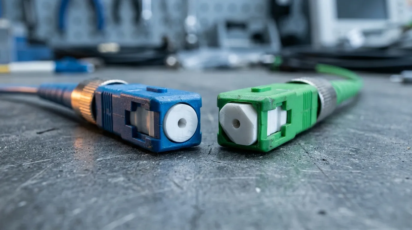
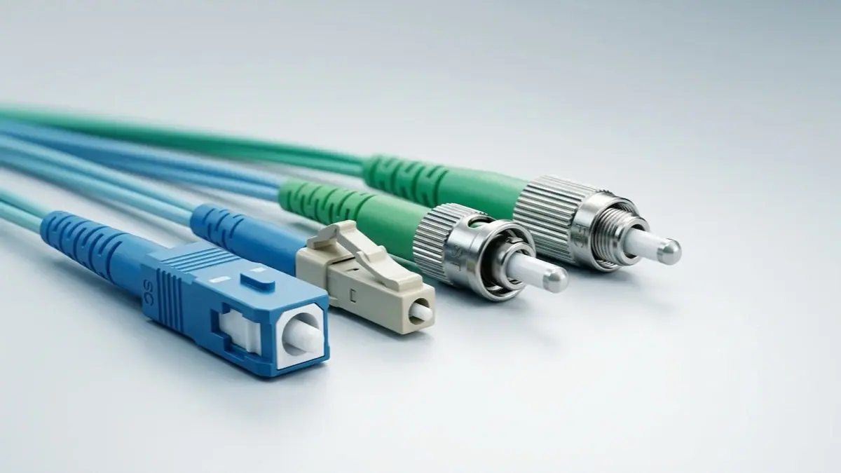
The photograph is the whole argument: the blue connector's ferrule sits square to the axis, the green one is cut at an angle. That angle is lapped at the factory, which is why polish is the one axis you cannot change after delivery.
The rule that costs the most money when broken: never mate APC to UPC. An 8° angled end face brought against a flat 0° end face leaves an air gap and the two cores meet at an angle; insertion loss jumps, back-reflection returns, and the ferrule can be chipped. The damage is not always visible without an inspection scope, which is why the color convention (green vs blue) exists and why mixing them is a rookie error that experienced buyers still make once. PC and UPC, by contrast, are both 0° convex and mate with each other safely — a UPC cord in an older PC panel works, at the lower of the two return losses.
Choose APC when the link is analog or wavelength-division multiplexed, when the loss budget is tight, or when the hardware already has green ports. Choose UPC everywhere else. The deeper comparison of geometry and measured performance is in our APC vs UPC guide.
Axis 5: Jacket and Fire Rating
Jacket is the axis most often bought by habit and rejected at inspection. Two different things get conflated: the material (what the jacket is made of) and the rating (what test the cable passed).
Materials first. PVC is the cheapest and most common general-purpose jacket. LSZH — low smoke zero halogen — burns without producing corrosive halogen acids and with much less smoke, which is why it is widely specified in tunnels, rolling stock, ships and much European indoor work. LSZH is a material property; it is not, by itself, a fire rating that satisfies a US inspector.
Ratings second, and they are jurisdictional:
Rating | Test basis | Where it is required |
|---|---|---|
OFN | General-purpose, NEC Article 770 | General-purpose horizontal runs, trays and ducts; not permitted in risers or plenum spaces |
OFNR | Riser-rated | Vertical shafts between floors |
OFNP | Plenum-rated, NFPA 262 Steiner tunnel | Air-handling ceiling voids and ducts |
CPR class (Cca, B2ca, Dca, Eca) | EN 50575, reaction-to-fire classes | EU/UK projects, specified as a class plus a smoke/acid suffix |
The US side is enforced through the NEC and tested to NFPA 262 for plenum cable. The European side is enforced through the Construction Products Regulation, Regulation (EU) 305/2011, which made CE marking of reaction-to-fire performance mandatory for cables sold into EU buildings. They are not equivalent scales, and a supplier quoting "LSZH" answers neither question on its own.
Practically: a plenum return-air ceiling needs OFNP, full stop — an LSZH cord without the plenum test is not compliant and will be pulled out. A European riser may need Cca-s1b,d1,a1 rather than "LSZH". If the requirement is unfamiliar, our explainers on LSZH vs PVC vs plenum jackets and CPR cable classes break the two systems apart.
There is also a diameter consequence nobody mentions in the catalog: plenum and LSZH compounds are bulkier than PVC, so a 24-cord bundle in a 1U panel may not close its door with the plenum-rated version of the same cord. Order one sample bundle before committing a whole floor.
One construction option belongs to this axis even though it is not a rating: armored patch cords, where a stainless steel or aramid layer sits between the fiber and the outer jacket. Armored cords are specified where the route is exposed — floor voids, industrial cabinets, anywhere a rodent or a boot can reach the cable — and they are heavier and stiffer at the same length. They do not replace a fire rating; an armored cord still has to be OFNR, OFNP or the right CPR class for the space it runs through.
Axis 6: Length, Tolerance and Loss Budget
Length looks like the simplest decision and is the one most often under-specified.
Stock lengths — 1, 2, 3, 5, 10 m — cover patching inside a rack and across a room. Once a cord leaves the rack, stock lengths stop working: a 3 m cord in a 2.7 m route puts the bend radius at risk, and a 5 m cord in a 3 m route leaves a coil that someone will eventually hang on a hook. Custom lengths exist precisely for this and cost a premium per unit at low quantities.
What matters on a custom order is the tolerance, because the manufacturer is going to build to a drawing and the route does not negotiate. Most factories publish a tolerance somewhere between ±10 mm and ±100 mm on assemblies, and the tighter number costs more. Ask for the tolerance in writing and check it against the slack you actually have. A cord ordered "3 m" that arrives at 2.95 m is not defective — it is compliant with a tolerance nobody wrote down.
Then the loss budget. Each mated pair contributes insertion loss; 0.3 dB is a realistic planning figure for a good LC or SC connection, and the standard permits more. Two connectors per cord means every cord you add to a channel spends budget. A 100GBASE-SR4 channel budget is under 2 dB, and the standard allowance on OM3 is 1.8 dB — six mated pairs at 0.3 dB each spend that entire allowance, before any margin. If your design has cords, cassettes, adapters and a patch panel in series, count the pairs before you choose a cheaper connector grade.
The counter-case is worth stating, because this guide argues for precision: over-specifying costs money too. APC everywhere on short intra-rack links, or a custom length where a stock cord plus a service loop would do, adds price without adding margin. Specify what the link needs, not the tightest tolerance available.
Bend radius belongs here too. Installed, a patch cord should not bend tighter than about ten times its outer diameter; under pull, twenty times. Bend-insensitive fiber (ITU-T G.657) tolerates far tighter radii, which matters in dense cabinets where cords are folded behind doors — but it does not excuse a 90° kink at the boot.
Where the Cord Lives: Data Center, Enterprise Room, FTTH Drop
Three locations account for most of the cords sold, and each pushes a different axis to the front. If you only read one paragraph before ordering, read the one that matches your site.
In a data center, the cord is short, dense and nearly always LC duplex or an MPO trunk feeding cassettes. Density drives the connector decision: LC because SFP and QSFP cages take it, MPO because 40G, 100G and 400G run over 4 or 8 lanes and one ferrule replaces four or eight duplex cords. Polish is normally UPC — a short multimode link does not need the return-loss headroom APC buys. The failure mode that bites here is polarity, not length.
In an enterprise telecom room, the cord spans a rack or a floor: LC or SC between patch panels and switches, often over OM3 or OM4 that was installed years before the electronics. Cords are the cheapest way to introduce a mode mismatch into that plant, which is why the color code does the real work. Jacket class starts to matter at this layer, because the cord may leave the room.
At the FTTH drop, the cord is short, single-mode, and SC/APC almost without exception — PON optics and the video overlay are the reason APC exists. Jacket class follows the building, and because the cord is replaced by a field technician rather than a data-center team, connector handling and dust caps matter more than loss headroom.
Location | Dominant assembly | What decides it | The usual mistake |
|---|---|---|---|
Data center | LC duplex, or MPO trunk with breakouts | Rack density and optics lane count | Polarity type ordered by assumption |
Enterprise telecom room | LC or SC duplex, OM3/OM4 | Existing cable plant and panel hardware | Mixing multimode grades on one link |
FTTH drop | SC/APC simplex or duplex, OS2 | PON optics and building fire class | UPC ordered where the OLT port is APC |
What to Write on the Order
Six axes become one line on a purchase order. The grammar is consistent across the industry and reading it backwards is how you audit a quotation:
Field | What to write | Why it matters |
|---|---|---|
Connector | LC, SC, ST, FC or MPO, and the housing gender for MPO | Wrong family does not seat |
Polish | UPC or APC | Cannot be changed after manufacture |
Mode and grade | OS2, OM3, OM4, OM5 | Sets reach and color |
Fiber count | Simplex, duplex, or 8/12/16/24 | Sets lane count and harness type |
Jacket | LSZH, PVC, OFNR, OFNP, or CPR class | Compliance, not preference |
Length and tolerance | Meters plus the allowed variation | The route does not stretch |
Test data | Insertion loss and return loss per end | The only evidence you will get |
A complete line reads like this: LC/UPC to LC/UPC, duplex, OS2 9/125, LSZH, 3.0 m ±50 mm, IL ≤0.30 dB, RL ≥50 dB, test report per assembly. Every field in that sentence is a decision you have already made; nothing is left to the supplier's default. That line is what turns an LC fiber optic patch cord from a guess into a part number.
Two numbers are worth extracting from any supplier before you compare quotes, because they are the ones that differ: the insertion-loss limit per connector and the length range the factory will actually build. TTI Fiber publishes ≤ 0.2 dB typical and ≤ 0.3 dB maximum per connector, return loss ≥ 50 dB (UPC) or ≥ 60 dB (APC), and custom assemblies from 0.3 m to 100 m. Both are measured quantities, so the method matters: return loss is measured to IEC 61300-3-6, and connector attenuation to IEC 61300-3-4. Ask for the test method alongside the number — an insertion-loss figure without its measurement standard cannot be compared across suppliers.
Incoming inspection is the other half. Check the end faces with a scope before the cords go into service — a contaminated connector damages the port it mates with, and the damage is not covered by anyone's warranty. Verify the test report exists and matches the serial numbers on the labels. Confirm the jacket print matches the rating you ordered, because that print is what an inspector reads. And spot-check length on a few units against the drawing tolerance.
TTI Fiber builds patch cords to this kind of specification — connector, polish, mode, jacket and length as stated on the drawing, with loss test data per assembly. Custom builds start at MOQ 50 pieces with a 3-day lead time, and standard orders run on a same-week production schedule. If the cords are going into a panel rather than straight into a switch, the panel's own constraints are covered in our fiber patch panel selection guide.
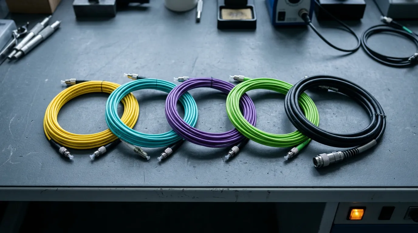
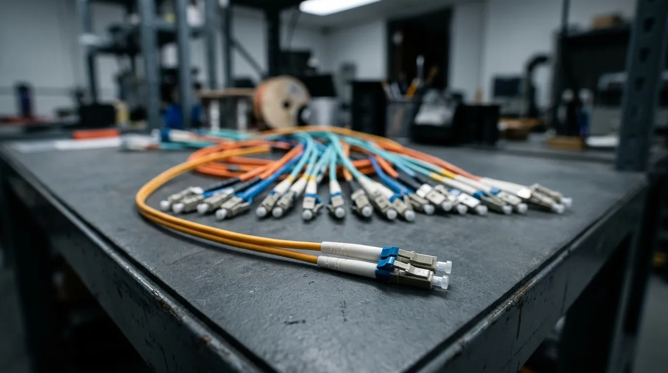
The colors in that photo are the whole mode decision in one glance: yellow is OS2 single-mode, aqua is OM3/OM4, violet is OM4, lime is OM5, and the black armored cord is the one that goes where a rat can reach it.
Five Mis-Buys That Cost the Most
1. APC mated into UPC. The classic. Loss spikes, reflections return, and a scope inspection shows chipped ferrules on both sides. Cost: two cords and sometimes the adapter. Prevention: color check at goods-in, every time.
2. Polarity bought by assumption. An MPO trunk of the wrong polarity type turns a 12-fiber link into a set of dead lanes. It is not a manufacturing fault and it is not always returnable. Cost: re-termination or a replacement trunk plus a re-test. Prevention: know the type (A, B or C) before ordering and confirm it on the harness label.
3. Jacket class treated as a material choice. "LSZH" ordered into a plenum ceiling is the single most common compliance rejection in new buildings. Cost: re-pulling a floor, because the inspector will not sign. Prevention: get the space class from the building's fire strategy, not from the last project's BOM.
4. Mode mismatch at the transceiver. A multimode cord between single-mode ports will not pass light usefully — and the reverse case damages nothing but wastes the run. Cost: a re-order and a lost day. Prevention: color code plus a label on both ends.
5. Length ordered without tolerance or slack. Cords that are 5 cm short force a panel to move; cords with 2 m of excess get coiled and kinked behind a door. Cost: re-work at the worst time. Prevention: measure the route, not the rack, and write the tolerance on the order.
Every one of these is a specification failure, not a quality failure. That is the argument for the six-axis order: it forces the decisions into the quotation, where they cost minutes, instead of into the installation, where they cost days.
FAQ
Is a patch cord the same as an Ethernet cable? No. An Ethernet cable is copper twisted pair carrying electrical signals; a fiber patch cord carries light and cannot be plugged into an RJ45 port. Within fiber, a patch cord and a fiber patch cable are two names for the same assembly — the cable houses call it a cable, the network houses call it a cord, and nothing about the build changes. They serve the same architectural role — a short run between two pieces of equipment — on different media.
Can fiber optic cable be patched? That is exactly what a patch cord is for. The cord terminates both ends at connectors so the link can be re-routed at an adapter panel without touching the permanent cable.
Simplex or duplex — which do I need? Duplex, unless the optics are bidirectional and use one strand. If your transceiver datasheet shows a single optical port with two wavelengths, you need simplex; if it shows Tx and Rx ports, you need duplex.
SC or LC — which is better? Neither is better; they fit different hardware. LC gives roughly twice the port density and is what SFP and QSFP cages take. SC is easier to handle and clean and remains the access-network standard.
Choosing Is the Whole Job
The cord itself is a small line item. The specification behind it is where the money sits — in re-orders, in re-pulls, in inspection failures and in links that test 1.5 dB worse than the design predicted.
Work the six axes in order, write them on the order, and check them at goods-in. That sequence is the entire difference between a commodity purchase and a specified one.
If you would rather hand the six axes to a factory and get a tested assembly back, the build options — connector, polish, mode, jacket, length and per-assembly loss data — are on the fiber optic patch cord product page.