MPO Type A vs Type B: Polarity Explained
MPO Type A vs Type B is really a question about one thing: which fiber at one end of a link lands on which fiber at the other end, and whether the connector key is on the top or the bottom of the housing when it does. Get it right and a 400G channel lights up on the first try. Get it wrong and you get a link that passes every loss test and still carries no traffic.
This guide gives the exact mapping for all three polarity types, the full twelve-position pin tables most vendor pages skip, and the piece that decides the answer on a real bill of materials — the polarity method your ports and adapters are built around. If you already know Type A is straight-through and Type B is reversed, skip to the mapping table; if you are still deciding what to put on a purchase-order line, read straight through.
MPO Type A vs Type B: The Short Answer
Type A is straight-through: the connector key is up on one end and down on the other, so position 1 arrives at position 1 and nothing crosses. Type B is fully reversed: both connector keys are up, so position 1 arrives at position 12 and the whole array is mirrored. Type C flips adjacent pairs only — 1 to 2, 2 to 1, 3 to 4 — which is why it is primarily used for duplex breakout rather than as a standard plug-and-play solution for parallel optics. For 40G, 100G, 400G and 800G links that run parallel lanes between two transceivers or two modules, Type B is the default; for MPO-to-LC cassette and structured-cabling plants, Type A trunks with polarity correction at the cassette are the norm.
The distinction that trips people up is that Type describes a cable's internal geometry, while Method describes how a whole channel is assembled from trunk, patch cords and adapters. A Type A cable may be used in a channel designed around another polarity method only when the complete end-to-end mapping is intentionally engineered and documented; it is not automatically a Method B component. In the conventional Method A parallel-optics recipe, a straight Type A trunk is combined with exactly one Type B polarity element at one end to provide the required Tx/Rx reversal. We will separate the two properly in a moment.
Type A | Type B | Type C | |
|---|---|---|---|
Mapping | 1→1, 2→2 … 12→12 | 1→12, 2→11 … 12→1 | 1↔2, 3↔4 … 11↔12 |
Connector keying | key up ↔ key down | key up ↔ key up | key up ↔ key down |
Best fit | cassettes, structured cabling | parallel optics, direct MPO-to-MPO | duplex LC breakout (legacy) |
Parallel-optics safe | with a crossed patch cord | yes, by design | Not as a standard plug-and-play method; custom crossover engineering is required |
What MPO Polarity Actually Is (and Why a Wrong Map Kills the Link)
Polarity is not a property of a connector, a patch cord or a trunk. It is a property of the entire channel — the trunk, the patch cords at both ends, the adapters in between and the transceiver ports they land on. Every one of those elements either preserves or inverts the fiber order, and the only requirement that matters is that, across the whole chain, each transmit lane arrives on the far end's matching receive lane.
That is why a wrong polarity is invisible to a power meter. You can measure excellent insertion loss and return loss on every segment and still have a dead channel, because loss testing only proves that light gets through — not that lane 1 arrived at lane 1. The failure mode is a mapping error, not an attenuation problem.
Four physical details govern the mapping:
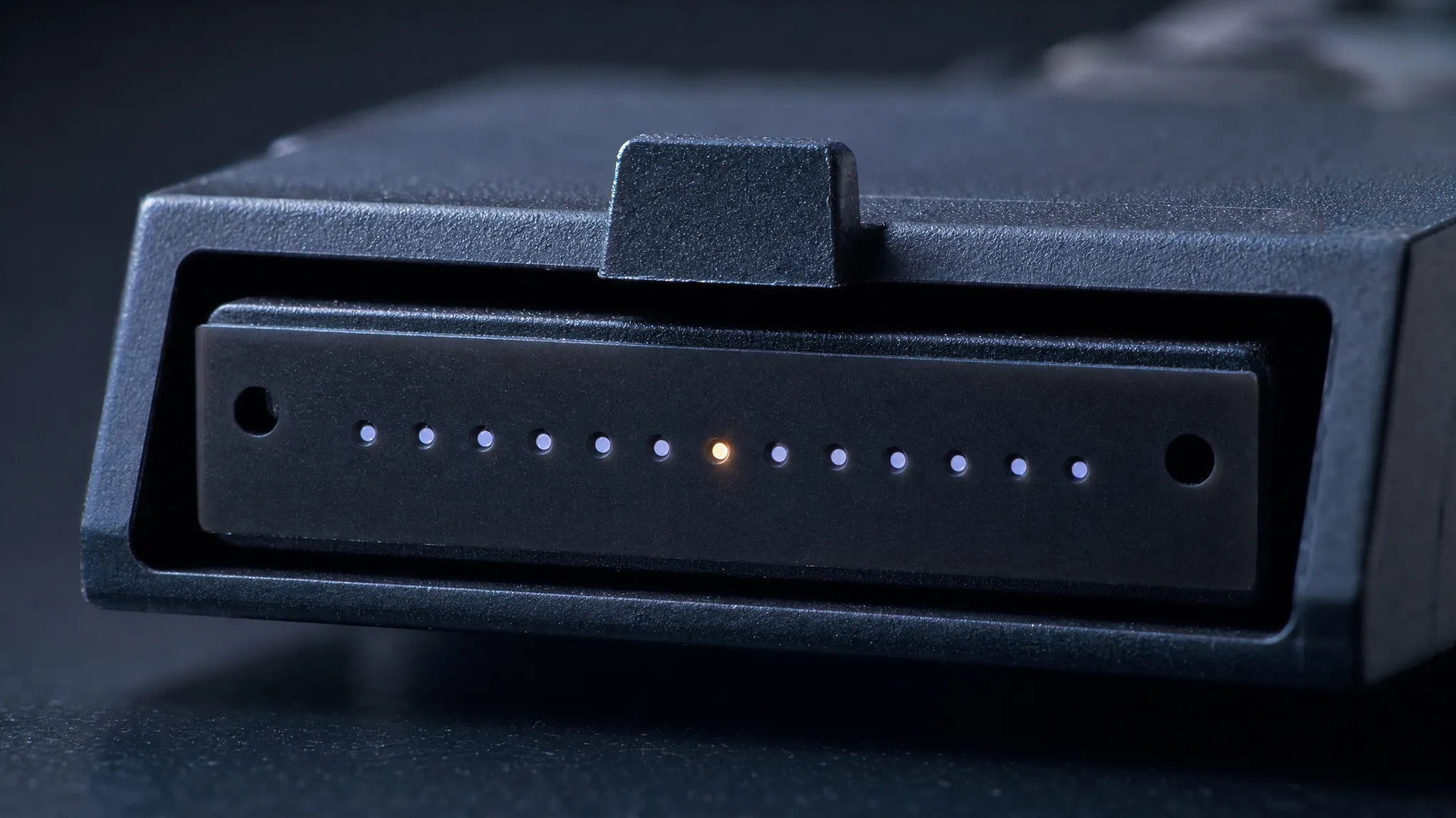
- The key. An MPO connector has an alignment key on one side of the housing. The key cannot be inserted the wrong way round, so its up-or-down position decides which numbered fiber position faces which position across the adapter. "Key up" simply means the key sits at the top when you look at the connector end face (SENKO's TIA-568 polarity reference describes the orientation the same way).
- The white dot. A small white dot on the connector side marks position 1. Everything else is counted from there.
- The numbered positions. MPO connectors carry 8, 12, 16, 24 or more fibers in one (or two) precision rows; 12 positions is the classic enterprise case and the one the tables below use.
- Gender. MPO interfaces are male (with alignment pins) or female (without). Active equipment interfaces are normally male, so the patch cord that plugs directly into a transceiver is normally female (unpinned) to avoid pin damage at that interface — a detail that is separate from polarity but is checked on the same purchase order.
The polarity rules themselves come from two standards families. ANSI/TIA-568.3-E defines the conventional A, B and C methods and the newer U1 and U2 universal methods for array-based polarity and migration. This article focuses on A, B and C because the Type A, Type B and Type C cable mappings and the commonly used parallel-optics channel recipes are built around them; U1 and U2 are additional methods used mainly for array-based duplex and migration scenarios. Key-up-to-key-up adapters are associated with the conventional Type B arrangement only when the connector end-face and mating geometry permit it; APC interfaces require the vendor-specified compatible key orientation and adapter, often in a modified Method B arrangement. IEC 61754-7 defines the MPO connector interface itself. When a vendor says "Method A" or "Type B", that language is coming from TIA-568, not from the connector standard. If you want the broader cabling context this sits inside — backbones, cassettes, trunks and the rest of the plant — our data center fiber cabling hub collects it, and the connector family itself is covered in fiber optic connector types.
MPO Type A Polarity: Straight-Through, Key-Up to Key-Down
A Type A assembly is straight-through. To build it, the connector at one end is fitted key up and the connector at the other end is fitted key down. Because the two ends are rotated 180° relative to each other, the numbering runs the same way on both sides and nothing crosses inside the cable. That geometry is described the same way in Fluke Networks' 12-fiber MPO polarity primer, which remains one of the cleanest short treatments of the three types.
The full mapping for a 12-fiber Type A trunk or patch cord:
Position at end 1 | 1 | 2 | 3 | 4 | 5 | 6 | 7 | 8 | 9 | 10 | 11 | 12 |
|---|---|---|---|---|---|---|---|---|---|---|---|---|
Arrives at end 2 | 1 | 2 | 3 | 4 | 5 | 6 | 7 | 8 | 9 | 10 | 11 | 12 |
Type A is the natural fit for structured cabling and cassette-based plants. Cassettes and modules are built to correct the lane order internally, so a straight trunk is all they need — and a straight trunk is the cheapest, simplest assembly to manufacture and the easiest to test. That simplicity is also Type A's trap: on a parallel-optics link it does not correct anything by itself, so the Tx/Rx swap has to happen somewhere else in the channel, which is exactly what a single Type B patch cord is for (see the method table below).
MPO Type B Polarity: Reversed, Key-Up to Key-Up
A Type B assembly is fully reversed. Both connectors are fitted key up, and because two key-up connectors meeting face to face mirror each other across the adapter, the fiber order inverts end to end. Position 1 arrives at position 12.
The full mapping for a 12-fiber Type B trunk or patch cord:
Position at end 1 | 1 | 2 | 3 | 4 | 5 | 6 | 7 | 8 | 9 | 10 | 11 | 12 |
|---|---|---|---|---|---|---|---|---|---|---|---|---|
Arrives at end 2 | 12 | 11 | 10 | 9 | 8 | 7 | 6 | 5 | 4 | 3 | 2 | 1 |
That single built-in reversal is why Type B is the workhorse of parallel optics. A 40G, 100G, 400G or 800G link that runs straight from one transceiver or module to another needs the lane order inverted exactly once across the whole channel. A Type B trunk does that inversion inside the cable, so the patch cords at both ends can be the same type as each other and no one has to remember which end takes which cord. It is also a common default for new direct parallel-optics builds: fewer part numbers and fewer ways to get the mapping wrong. A conventional Method B arrangement can support a direct transceiver-to-transceiver MPO connection without a separate crossover assembly, provided that the complete lane map, connector gender, end-face polish, adapter geometry and transceiver interface are compatible.
MPO Type C Polarity: Pair-Flipped — and Why Parallel Optics Usually Avoids It
Type C sits between the other two. The connectors are keyed like Type A — key up on one end, key down on the other — but inside the assembly the fibers swap in adjacent pairs rather than one by one or all at once.
The full mapping for a 12-fiber Type C trunk:
Position at end 1 | 1 | 2 | 3 | 4 | 5 | 6 | 7 | 8 | 9 | 10 | 11 | 12 |
|---|---|---|---|---|---|---|---|---|---|---|---|---|
Arrives at end 2 | 2 | 1 | 4 | 3 | 6 | 5 | 8 | 7 | 10 | 9 | 12 | 11 |
Type C exists to solve the duplex problem: in a legacy duplex link where every pair of fibers carries one transmit and one receive, swapping pairs inside the cable removes the need for a crossed patch cord at the transceiver. It works cleanly for that.
Type C is not a plug-and-play choice for parallel optics. A 4-lane parallel link expects the active lanes in positions 1–4 at one end to arrive at positions 9–12 at the other end in the required order. Because Type C swaps adjacent fiber pairs, the lane order is scrambled rather than fully reversed. A Type C-based parallel channel can be engineered with a custom crossover assembly and a complete end-to-end mapping, but the additional components and limited availability make it unsuitable for most new parallel-optics deployments. That is the honest reason Type C is described as legacy: it is a duplex solution that the industry's shift to 8- and 16-fiber parallel links quietly left behind.
Type A vs Type B vs Type C: The Mapping Side by Side
Here is the whole comparison in the form a specifier actually needs it — mapping behavior, keying, and the adapter that must sit between the cables.
Polarity type | Internal mapping | Connector keying | Adapter that pairs with it | Parallel-optics safe? | Typical use |
|---|---|---|---|---|---|
Type A | Straight-through (1→1 … 12→12) | Key up ↔ key down | Type A adapter (mates key-up to key-down) | Only with a crossed patch cord | MPO-to-LC cassettes, structured backbone |
Type B | Fully reversed (1→12 … 12→1) | Key up ↔ key up for the cable assembly | Type B-compatible adapter for compatible connector geometry; APC builds may require an opposed-key adapter in a modified Method B arrangement | Yes | when the complete channel mapping, connector gender, polish and adapter geometry are compatible |
Type C | Pairwise flip (1↔2, 3↔4 …) | Key up ↔ key down | Type A adapter (key-up to key-down) | No | Duplex LC breakout, legacy |
The adapter column is the one most articles leave out, and it is the one that causes field damage. The keying of the adapter has to match the cable type you plug into it. Type A and Type C assemblies commonly use opposed-key adapters, while a conventional Type B arrangement uses an aligned-key adapter when the connector end-face geometry permits it. For APC MPO interfaces, do not assume that a key-up-to-key-up adapter is suitable; follow the transceiver, connector and adapter manufacturer's approved polarity arrangement, which may use Type B cable components with opposed-key adapters. Force a Type B trunk into a standard adapter and one end has to be inserted rotated — which is how ferrules get scratched and alignment pins get bent. If an MPO connector will not seat with light finger pressure, check the key before you check anything else.
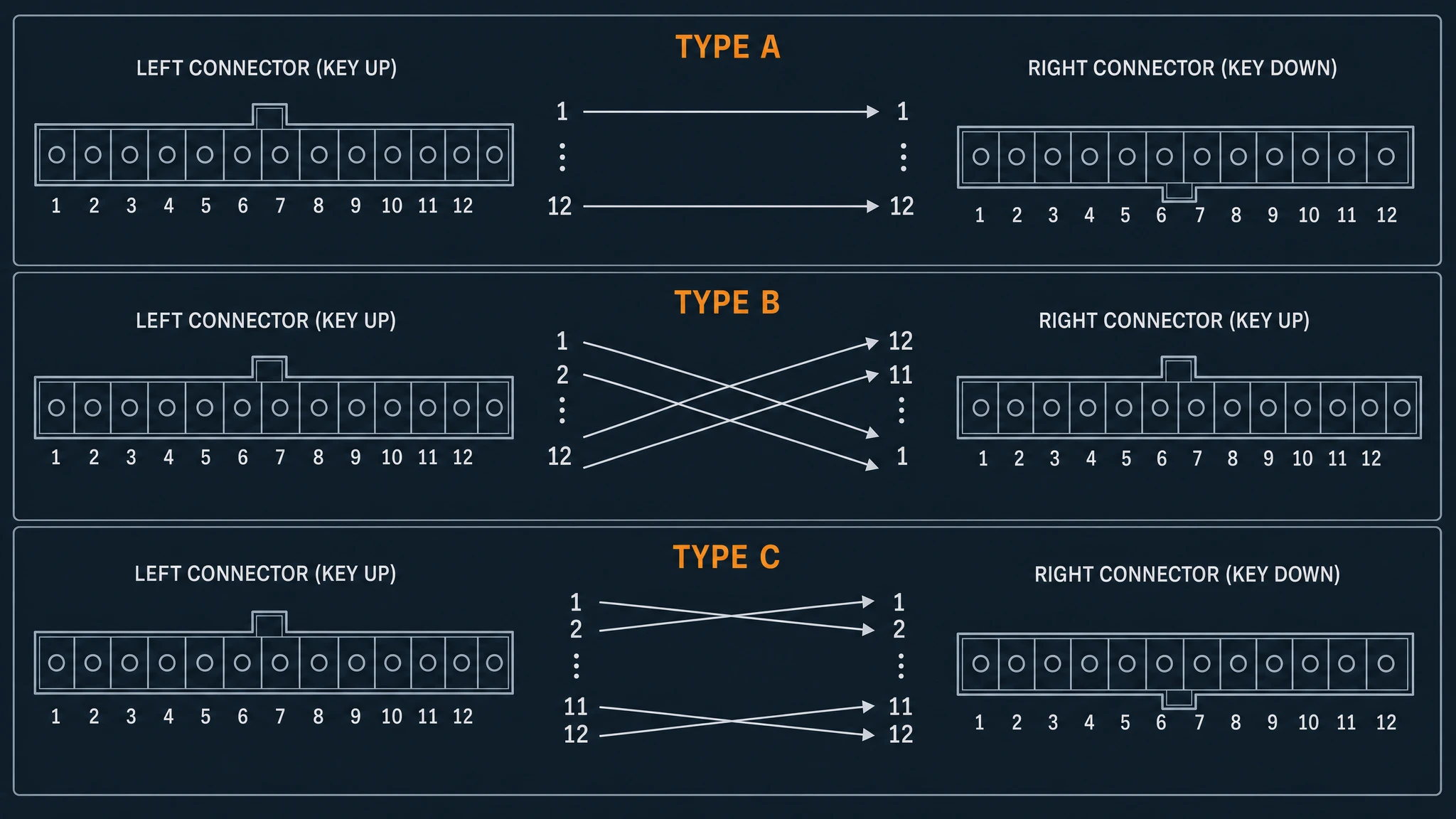
Type A keeps the array straight because the two connectors are keyed opposite; Type B reverses the whole array because both connectors are keyed up; Type C swaps only adjacent pairs.
The other thing this table settles is terminology. "Type" is a cable property; "Method" is a channel property. When a colleague says "we are a Method B shop", they are describing the recipe used across the whole plant — cable types and patch cords together — not a single part number. The next section is that recipe.
Which Polarity Method Matches Your Port Setup?
A polarity method is the component combination that makes one channel work. TIA-568.3-E now describes five polarity methods — A, B, C, U1 and U2. A, B and C are the conventional methods, while U1 and U2 are additional universal methods for array-based duplex and migration scenarios. The table below focuses on A, B and C because they are the conventional methods most commonly used to explain Type A, Type B and Type C MPO assemblies. The table below follows the standard combinations used for 10G duplex and for 40/100G parallel applications.
Method | Application | Patch cord, end 1 | Cable | Patch cord, end 2 |
|---|---|---|---|---|
A | 10G duplex | A-B | Type A | A-A |
A | 40/100G parallel | Type B | Type A | Type A |
B | 10G duplex | A-B | Type B | A-B |
B | 40/100G parallel | Type B | Type B | Type B |
C | 10G duplex | A-B | Type C | A-B |
C | Engineered parallel only — not recommended for new builds | Custom crossover assembly | Type C | Type B or other vendor-specified component |
Read the parallel-optics rows and the pattern is clear. Method A uses a straight Type A trunk, so the Tx/Rx flip has to be supplied by a single Type B patch cord at one end; TIA allows exactly one Type B patch cord in a Method A link, and a second one would flip the channel back and break it (Fluke Networks sets out the same rule in its 12- and 8-fiber polarity guidance). Conventional Method B uses Type B polarity components throughout the optical mapping, which simplifies parallel-optics deployment because equivalent patch-cord roles can use the same polarity. However, the adapter and cassette keying still depends on connector gender, end-face polish and the selected equipment interface. APC implementations may use a modified Method B arrangement rather than Type B key-up-to-key-up adapters.Method C is intended primarily for duplex applications. A parallel-optics channel based on Type C can be engineered with a custom crossover assembly, but it is not a standard plug-and-play configuration and is generally avoided in new high-speed builds.
That produces three practical rules for the plant:
- Pick one method and hold it across the whole data center. Mixed methods inside one cable plant are how "it worked in the lab" turns into a ticket. Most experienced cabling teams standardize on Method B for parallel zones because the uniformity removes cord-selection errors entirely.
- Direct transceiver-to-transceiver links commonly use conventional Method B or a vendor-approved modified Method B arrangement. The selected method must match the transceiver's MPO base, gender, end-face polish, adapter geometry and complete lane map.An MPO link that runs port to port with no cassette in between has nowhere else for the reversal to live. A Type A trunk between two transceivers does not provide the required parallel-optics reversal by itself; an approved Type B polarity element or another documented crossover must be included in the channel.
- Extending an existing Method B channel is where Type A earns its keep. Extending an existing Method B channel requires preserving the approved end-to-end Tx/Rx mapping. Do not decide the extension by counting Type B cable segments alone; include the polarity contribution of trunks, patch cords, adapters and cassettes. If the extension changes the mapping, select the required Type A or Type B component, or an approved conversion assembly, according to the documented channel design. This is the one place a Method B plant legitimately contains a Type A cable — and it is a common source of confusion when someone audits the plant later.
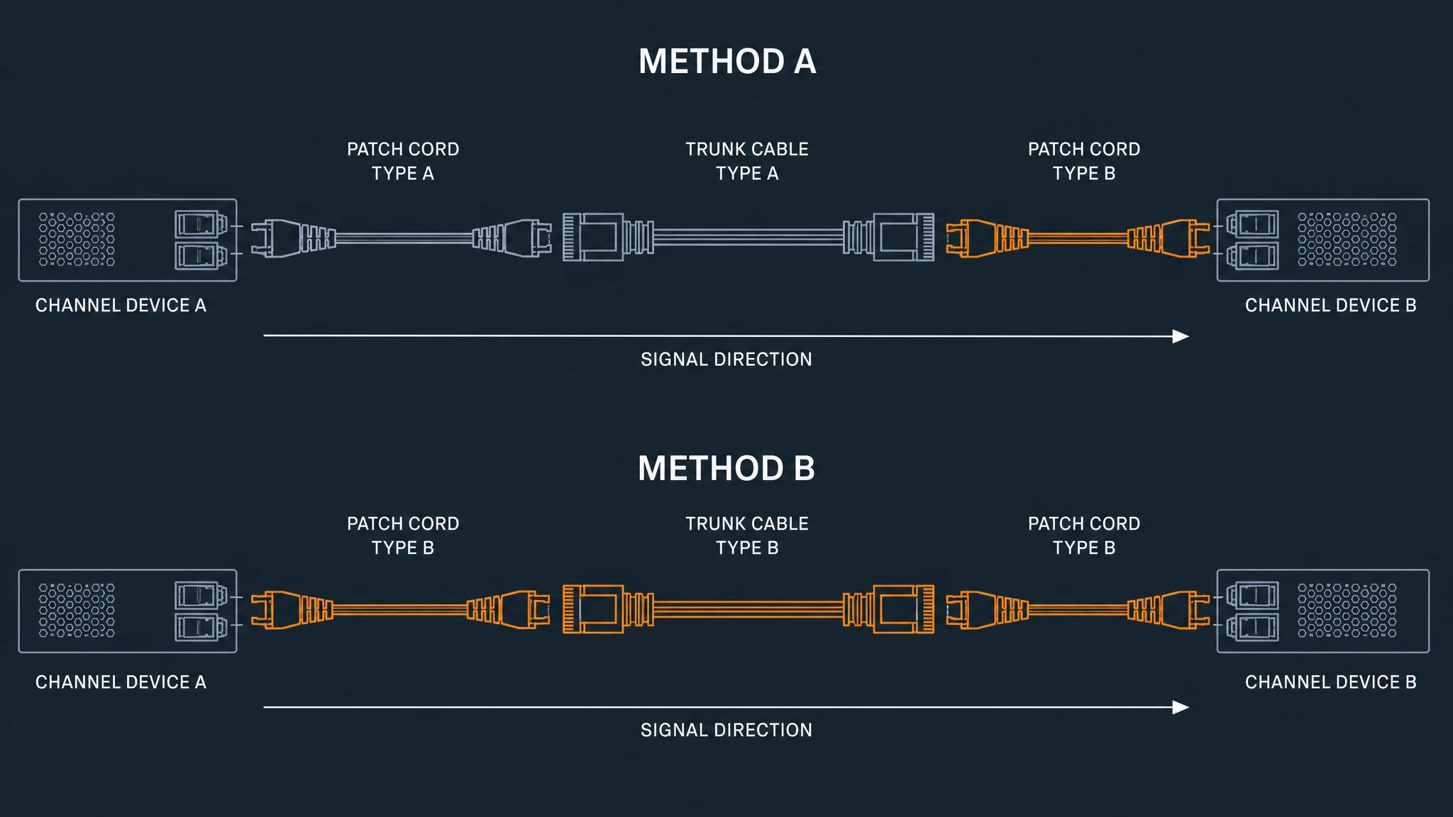
Method A places a single Type B polarity element at one end of a straight Type A trunk. Conventional Method B uses a documented combination of Type B polarity components so that the complete channel provides the required Tx/Rx mapping. Do not assume that the reversal occurs only inside the trunk; patch cords, adapters and cassettes can also affect the end-to-end mapping.
For a cassette-based plant the same logic applies with one extra step: the cassette or module is a polarity element too, and its internal mapping has to match the method. A cassette or module is itself a polarity element, so its internal fiber mapping must be specified as part of the complete channel method. A cassette with a straight-through internal mapping may be paired with a Type A trunk in the intended Method A arrangement; a cassette designed for Method B may require Type B components instead. Do not assume that every MPO-to-LC cassette performs the same polarity correction or that combining it with a Type B channel automatically creates a double correction. If you are putting together the assemblies for a specific method, TTI Fiber's MTP-to-MTP trunk cables and MPO-to-LC cassettes are specified by polarity and keying, so the method you chose travels with the part number rather than living in someone's memory.
Base-8, MPO-16 and 400G/800G: Polarity in the Parallel-Optics Era
None of the polarity rules above changed when the industry moved from 12-fiber to 8-fiber and 16-fiber connectivity. What changed is the number of lanes a link uses, and therefore how much of the connector is live.
The reason Base-8 exists at all is waste. The first parallel-optics deployments used 12-fiber MPO connectivity for 4-lane optics, which left the four center positions dark — a third of the installed glass doing nothing. The industry's answer was Base-8: the same connector footprint as a 12-fiber MPO but with the four center fibers removed, so eight fibers map one-to-one onto an 8-fiber link. Dedicated 8-fiber and 16-fiber connectors followed, and the family is now described by base: Base-8, Base-12, Base-16.
That matters for polarity because the mapping tables above are counted over live positions, and which positions are live depends on the base:
- Base-12 running 8-fiber optics — the eight active lanes occupy positions 1–4 and 9–12; the four center positions 5–8 carry nothing. A 24-fiber trunk built on this pattern is really three groups of eight, which is why 8-fiber applications on 12-fiber infrastructure often renumber through a conversion cassette or harness.
- Base-8 — eight fibers, mapped straight onto the eight lanes of a 4-lane parallel optic.
- Base-16 / MPO-16 — typically sixteen fibers arranged as two rows of eight, sized for links that use eight lanes each way.
That last one is where 400G and 800G live. A 400G-DR4 link uses four lanes each way, eight fibers in total. A 400G-SR8, 800G-SR8 or 800G-DR8 link uses eight lanes each way, which fills all sixteen positions of an MPO-16 with no waste. Each of those is still a parallel-optics channel and requires the correct end-to-end Tx/Rx lane mapping with the required number of polarity reversals. Type B components and Method B are common for direct parallel-optics links, but the final combination of trunk, patch cords, adapters, cassettes, connector gender and polish must match the transceiver interface. For APC MPO interfaces, use the vendor-approved modified Method B or other specified arrangement rather than assuming that every channel can use key-up-to-key-up adapters.
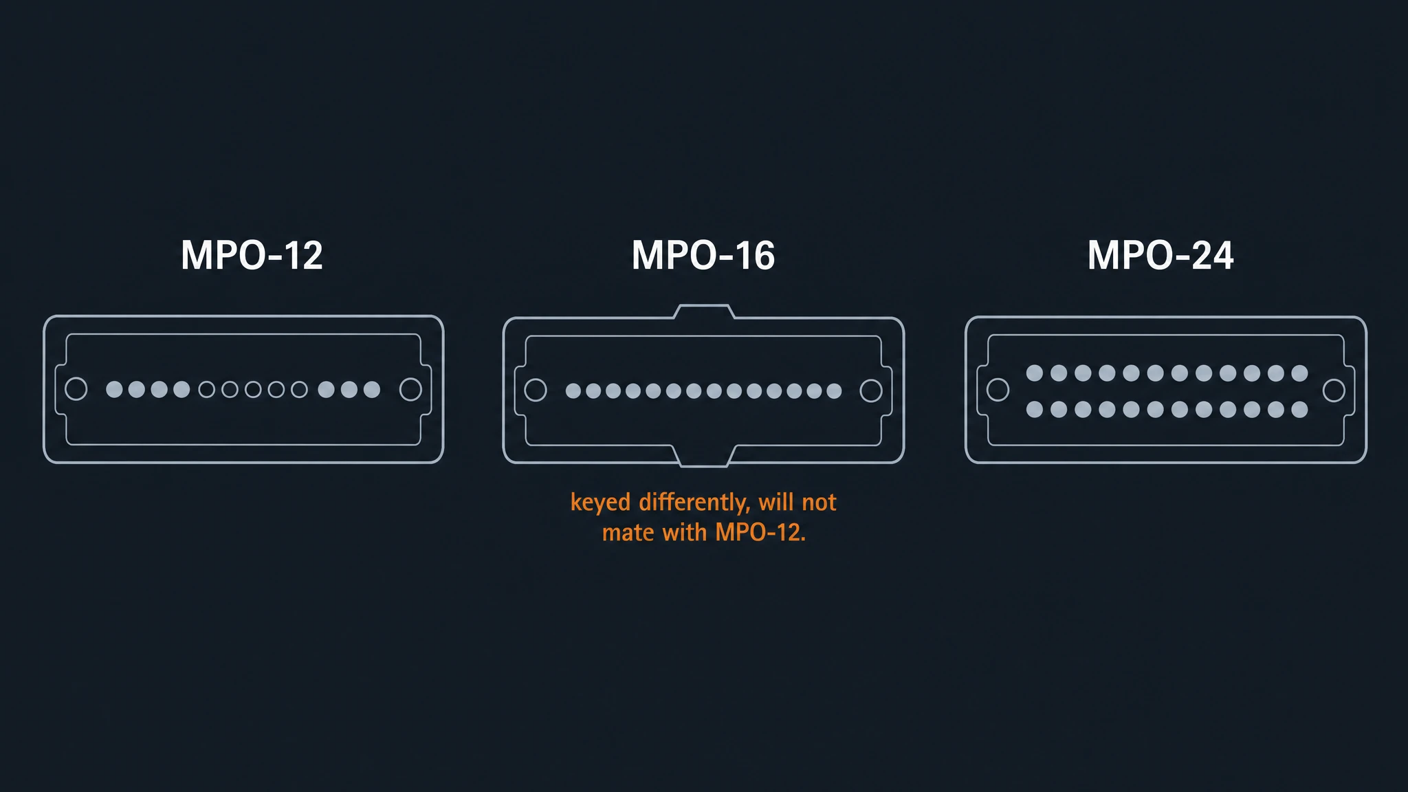
MPO-12 commonly uses a single row of fibers, while MPO-16 commonly uses two rows of eight fibers. An MPO-16 connector will not mate with an MPO-12 adapter because the fiber count, ferrule geometry and interface are different, even when the polarity method is the same.
There is one physical trap in the 400G/800G generation that has nothing to do with mapping and everything to do with keying: an MPO-16 will not mate with an MPO-12. The connector is not backward compatible, so a Base-16 migration needs its own adapters and its own harnesses even if the polarity method stays Method B. If the connector-count decision is still open — 12, 16 or 24 — the MPO-12 vs MPO-16 vs MPO-24 comparison works through the transceiver mapping that decides it, and the fiber grade behind those connectors is covered in OS2 vs OM4 vs OM5. Single-mode MPO adds one more constraint worth knowing before you order: Single-mode MPO connectors commonly use an angled physical-contact (APC) end face, and some high-speed multimode MPO interfaces also use APC. APC and UPC interfaces must not be mated. For APC MPO connections, the connector gender, key orientation and adapter geometry must all be compatible; matching the polish type alone is not sufficient. When a 400G or 800G build spans both short multimode reaches and longer single-mode ones, TTI Fiber's MPO harness cables are the usual way to fan a single high-density port out across the smaller connectors the endpoints actually use.
How to Verify Polarity Before You Dress the Cable
Polarity mistakes are cheap to find on a bench and expensive to find in a live row. The tell is distinctive: a channel that measures clean loss but passes no traffic. If a link tests well and stays dark, polarity is the first hypothesis, not the last.
A short sequence catches nearly all of it:
- Write the method on the drawing before you order anything. Trunk type, patch-cord type at each end, adapter type, cassette internal mapping. The most common cause of a polarity failure is not a wrong selection — it is no selection recorded anywhere, so the field installs whatever arrives.
- Put polarity, gender and polish on every purchase-order line. Trunks and patch cords are built to order and are often non-returnable, so the label is the documentation. Gender belongs on the same line: male (pinned) and female (unpinned) parts fail to mate just as hard as a wrong map.
- Match the adapter keying to the complete connector assembly. Type A and Type C assemblies commonly use opposed-key adapters, while conventional Type B PC/UPC assemblies commonly use aligned-key adapters. For APC MPO interfaces, do not assume that key-up-to-key-up is suitable; follow the approved adapter, connector and transceiver arrangement, which may use Type B cable components with opposed-key adapters. A connector that resists seating is telling you the keying is wrong — stop, do not push.
- Test cords and the assembled channel, not just the trunk. Polarity errors are introduced at the ends of a channel far more often than inside the permanent link, and a per-cord check catches the one flipped cord before it disappears into a bundle. Purpose-built multi-fiber test sets can scan all twelve fibers of a channel for continuity and polarity in seconds, which is the difference between finding the fault during installation and finding it after commissioning.
- Label both ends of every assembly with its type, and audit the first row. Polarity survives a data center on documentation, not on memory. The plant audit that follows a standardized Method B build is trivial; the audit that follows a mixed plant is a day of tracing.
Where the design allows it, field-changeable connector housings and polarity-change tools can rescue a wrong selection without re-ordering — the tool repositions the key rather than re-terminating the fiber. Treat that capability as insurance rather than as a specification strategy: it removes the delay from a mistake, but a plant still needs one planned method behind it. Once the method is set and labeled, the day-to-day work — patch cords, cassettes, trunks — stops being a puzzle. If you would like a second pair of eyes on the polarity scheme for a build, our team works through data-center cabling designs and can check a channel against the method you have chosen.
MPO Polarity FAQ
What are the different types of MPO cable? Three for polarity purposes: Type A (straight-through, key up to key down), Type B (fully reversed, key up to key up) and Type C (adjacent pairs flipped, key up to key down). Independently of polarity, MPO cables also come as trunk cables, harnesses and breakout cables, and in 8, 12, 16, 24 and higher fiber counts. If you are not sure which connector you are holding, a connector identifier tool is faster than counting fibers by eye.
Is MPO single-mode or multimode? Both. MPO connectors are built for single-mode and multimode fiber; the choice is set by the reach and the optic, not by the connector. Single-mode MPO uses an angled APC end face, while multimode is typically UPC — and the two must not be mated to each other.
Can I mix Type A and Type B in one channel? Not by accident.In the conventional Method A parallel-optics arrangement, the straight Type A trunk is combined with one Type B polarity element at one end to provide the required Tx/Rx reversal. A second reversal can cancel the intended mapping, so the complete channel must be checked rather than relying on the cable type alone. Keep one type per role, and record the method so the next person knows which role is which.
Which polarity do 40G, 100G, 400G and 800G links use? Parallel-optics links — including SR4 and DR4 at 40G/100G/400G, and SR8/DR8 at 400G/800G — commonly use Method B or a vendor-approved modified Method B arrangement. The required components depend on the MPO base, lane map, connector gender, end-face polish, adapter type and transceiver interface; do not specify Type B throughout the channel without checking the complete channel design. That includes 8-fiber links on MPO-8 or MPO-12 and 16-fiber links on MPO-16; the fiber count changes, the polarity rule does not.
Is Type C still used? For duplex LC breakout over legacy duplex backbones, yes. It is not recommended for parallel optics because the pairwise flip scrambles the lane order rather than fully reversing it. A Type C parallel channel can be engineered with a custom crossover assembly, but it is generally avoided in new high-speed builds because of the added complexity and limited availability of suitable components.
Does polarity change with the fiber count? No. A Type B mapping is a Type B mapping whether the connector holds 8, 12 or 16 fibers; what changes is how many positions are numbered and how many of them are live. Base-12 running 8-fiber optics uses positions 1–4 and 9–12 and leaves the center four dark.