MPO vs LC Connectors: High-Density Cabling
MPO vs LC is usually argued as a density contest, and MPO wins that contest every time. It is the wrong contest. The number that decides a cabling design is how many connector positions a fiber has to share — because that count sets your adapter count, your patch-cord count, how much of the channel's loss allowance the connectors eat, how many end faces you must clean and inspect, and how many channels go dark when one ferrule is contaminated. An MPO-24 puts 24 fibers on one position. Duplex LC gives every two fibers their own. Everything else in this comparison follows from that.
What follows is the arithmetic on both sides, the fiber counts the active equipment actually demands, where a connector's dB sits inside a channel budget, the failure modes a loss test will not catch, and an honest account of the links where LC is still the better answer. Skip to the at-a-glance table if you only need the summary.
What an MPO Connector Is, and What LC Is For
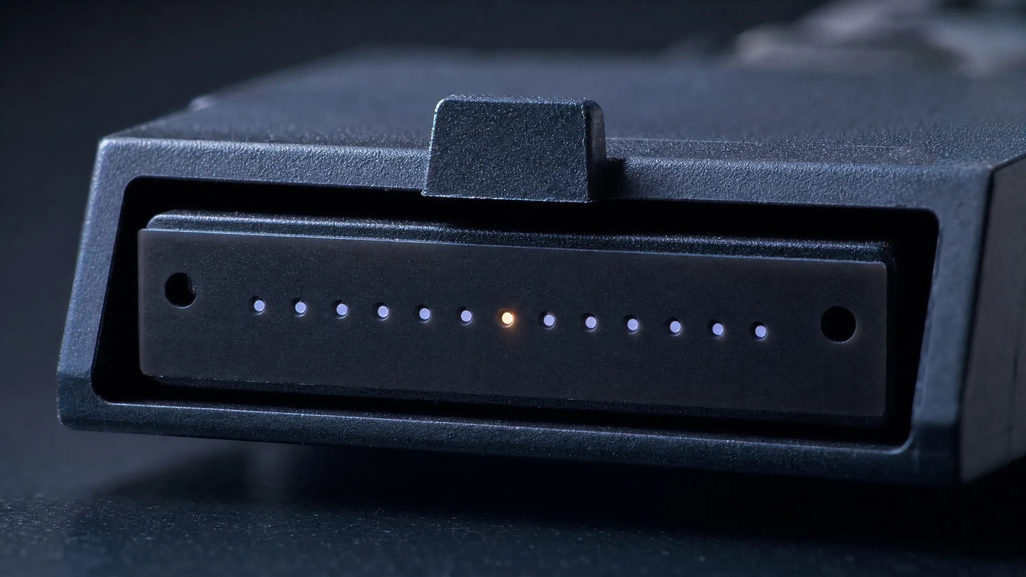
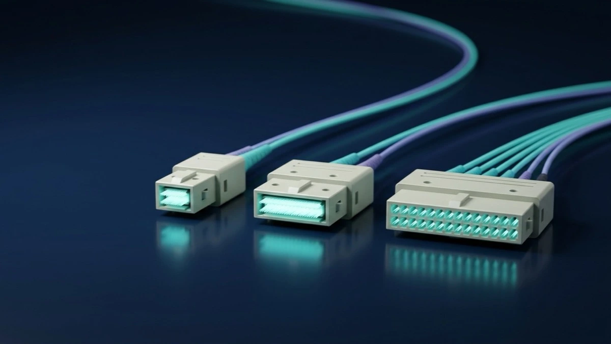
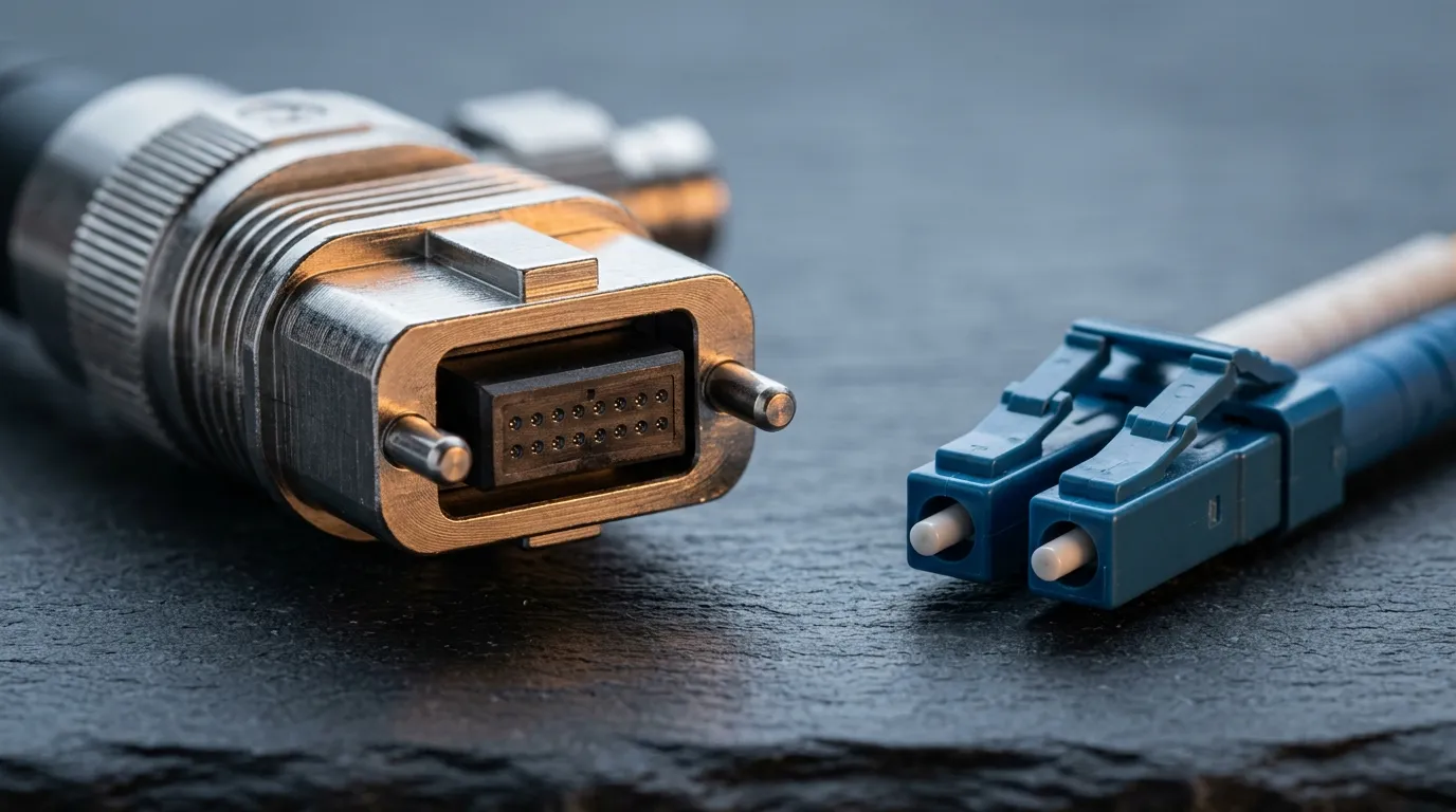
An MPO connector carries a whole ribbon in one keyed, rectangular ferrule. "MPO" stands for multi-fiber push-on. The ferrule is a rigid block holding a single row — or two rows — of fibers, and alignment comes from two guide pins on one connector locating into two guide holes on the other. IEC 61754-7-2 defines the two-row interfaces, with the one-row variants covering 2 to 12 fibers defined alongside it; in North America the same interfaces are pinned down for intermateability by TIA-604-5, known as FOCIS 5, with the 16-fiber version carried as FOCIS 18. The connector has a key, a male form with pins and a female form without, and an adapter that holds and aligns the pair.
MTP is not a competing interface. It is a registered trademark of US Conec for that company's own MPO-format connector, and MTP connectors mate with compliant MPO connectors because both follow the same interface standards. "MTP/MPO" is a naming convention, not a second geometry.
LC is a single-fiber connector that most often arrives as a pair. It uses a 1.25 mm nominal diameter ferrule and a single coupling latch. IEC 61754-20 standardizes the whole family — simplex, duplex and quad plug interfaces, in both physical-contact and 8° angled-contact forms — and the FOCIS register lists it as FOCIS 10. In practice a data center "LC port" means the duplex plug: a pair of simplex plugs on a duplex clip — two connector bodies, two latches, two ferrules, two fibers.
The boundary between the two is worth stating precisely, because most comparisons blur it. MPO carries 8, 12, 16 or 24 fibers per connection. LC carries one or two. SC is the other long-established two-fiber family, on 2.5 mm ferrules, and is not the contrast being drawn here. If you are unsure which physical part you are holding, the fiber optic connector types reference sorts them by latch, ferrule and keying, and the polish variants that confuse people most are covered in APC and UPC end faces.
MPO vs LC at a Glance
Dimension | MPO (multi-fiber push-on) | LC (Lucent connector) |
|---|---|---|
Fibers per connection | 8, 12, 16 or 24 in one MT ferrule | 1 simplex, 2 duplex |
Interface standard | IEC 61754-7-1 / -7-2; TIA-604-5 (FOCIS 5), FOCIS 18 for 16-fiber | IEC 61754-20; TIA-604-10 (FOCIS 10) |
Alignment | two guide pins into two guide holes | 1.25 mm cylindrical ferrule in a rigid or resilient sleeve |
Adapter positions for 24 fibers | 1 (MPO-24) | 12 (12 duplex plugs) |
Patch cords across a 24-fiber span | 1 | 12 |
Connector positions per fiber | shared with 11 or 23 neighbors | one position per fiber pair |
Polarity | key up / key down plus Method A, B or C | inherent in the duplex pair; hard to get wrong |
Field test and repair | array test set; damage means re-terminating an assembly | single-fiber test set; single-fiber re-termination |
Where the port leaves no choice | module ports for 40G/100G/400G/800G parallel optics | SFP/SFP+ access ports, server NICs, storage, out-of-band |
Cost shape | sits in the assembly: ferrule grade, pin count, factory test time | sits in per-port hardware and per-position field labor |
Three of those rows deserve more than a line each, and they are the next three sections.
The Adapter-Position Arithmetic Behind "High Density"
Density is not a property of a connector. It is a ratio, and the denominator is the position.
Take 24 fibers — one MPO-24 trunk, or the equivalent in duplex LC. As LC, those fibers are 12 duplex plugs, needing 12 adapter positions and 12 patch cords, and presenting 24 individual ferrules to be cleaned, inspected and tested. As MPO, the same 24 fibers are one plug, one adapter position, one patch cord and one MT end face. Nothing about the glass changed. The position count fell by a factor of twelve.
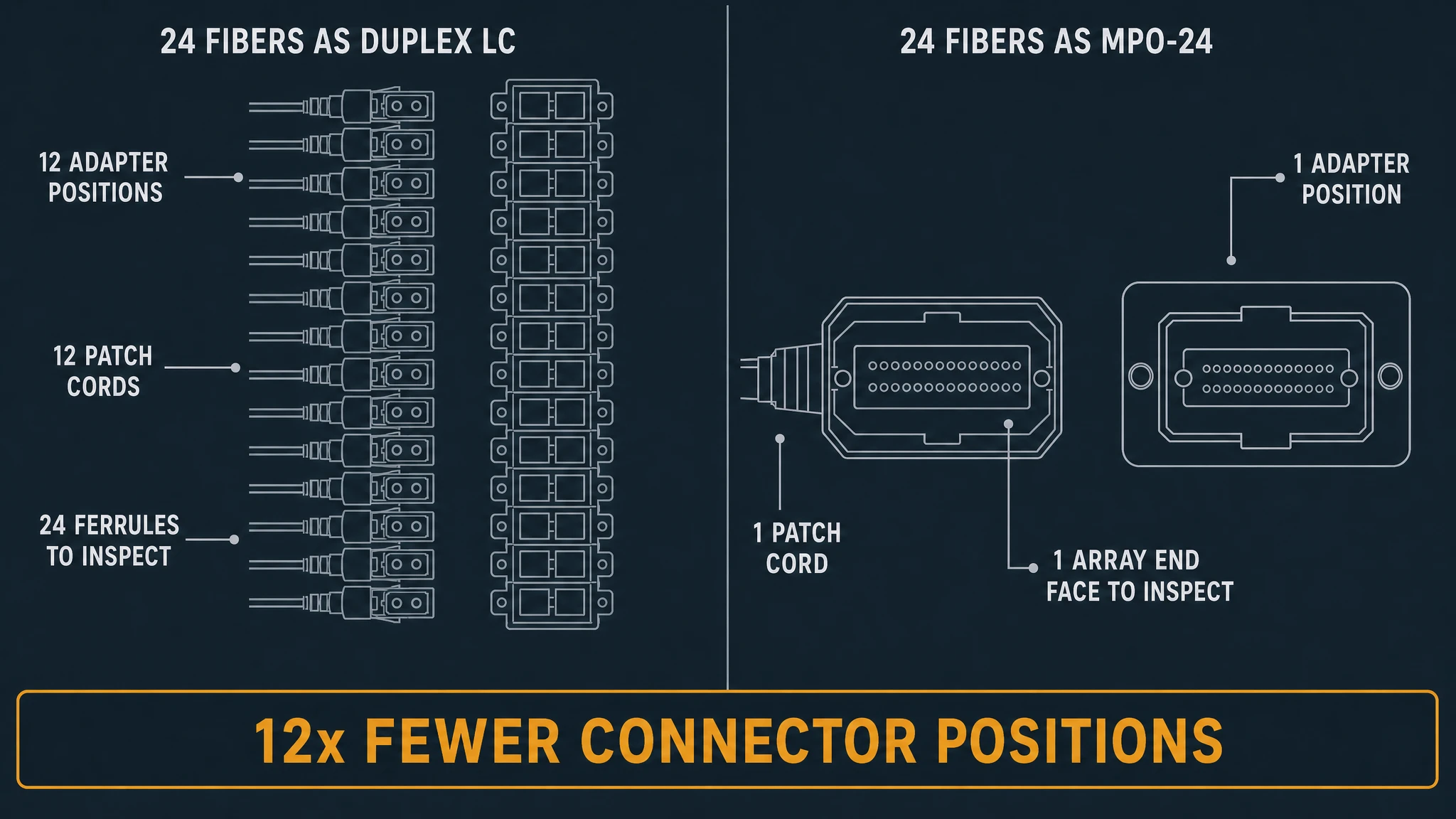
That ratio is what "high density" buys, and it lands in four places a bill of materials can see:
- Adapter and panel positions. Twelve LC adapters occupy twelve cut-outs; one MPO adapter occupies one. TTI Fiber's own 1U rack-mount ODF is specified at up to 24 LC duplex or 12 SC ports — a face limited by how many adapters fit on 19 inches. A panel that terminates its rear on MPO is limited by something else, because the fibers arrive already grouped.
- Patch-cord volume. Twelve cords become one. Vertical managers, tray fill and cabinet-front congestion scale with cord count, not fiber count.
- Inspection and cleaning events. One array end face replaces 24 ferrule end faces at that position. Fewer events, more fibers per event.
- Blast radius. The row that never appears in density marketing. A contaminated LC ferrule degrades one channel. A contaminated MT ferrule degrades every channel riding that array — 12 or 24 of them — and an array face offers far more surface for a stray particle than a 1.25 mm ferrule does.
Published "4x higher port density" claims from supplier case studies are a different class of number from a position count: unaudited project outcomes from the party selling the product, and not reproducible from a datasheet. The twelve-to-one ratio can be counted on a napkin, and it is the number to take into a design review.
Fiber Counts, Lanes and the Compatibility Trap
On a parallel-optics link, the fiber count is not a cabling preference. The active equipment defines it, and the cabling follows.
Ethernet application | Lanes | Fibers per channel | Module | Defined in |
|---|---|---|---|---|
40GBASE-SR4 | 4 | 8 | QSFP+ | IEEE 802.3ba (2010) |
100GBASE-SR4 | 4 | 8 | QSFP28 | IEEE 802.3bm (2015) |
10 | 20 | CXP, CFP | IEEE 802.3ba (2010) | |
400GBASE-SR8 | 8 | 16 | QSFP-DD, OSFP | IEEE 802.3cm (2020) |
4 (2 wavelengths) | 8 | QSFP-DD | IEEE 802.3cm (2020) | |
8 | 16 | QSFP-DD, OSFP | IEEE 802.3df (2024) |
Every one of those applications specifies a multi-fiber connector as its network-equipment interface. That table is also why the installed base is full of different arrays: 8 fibers for the four-lane generations, 20 fibers for 100GBASE-SR10 — which is why 24-fiber arrays were built — and 16 fibers once 400G and 800G went to eight 50G or 100G lanes. An MPO-12 vs MPO-16 vs MPO-24 walkthrough covers which array suits which generation.
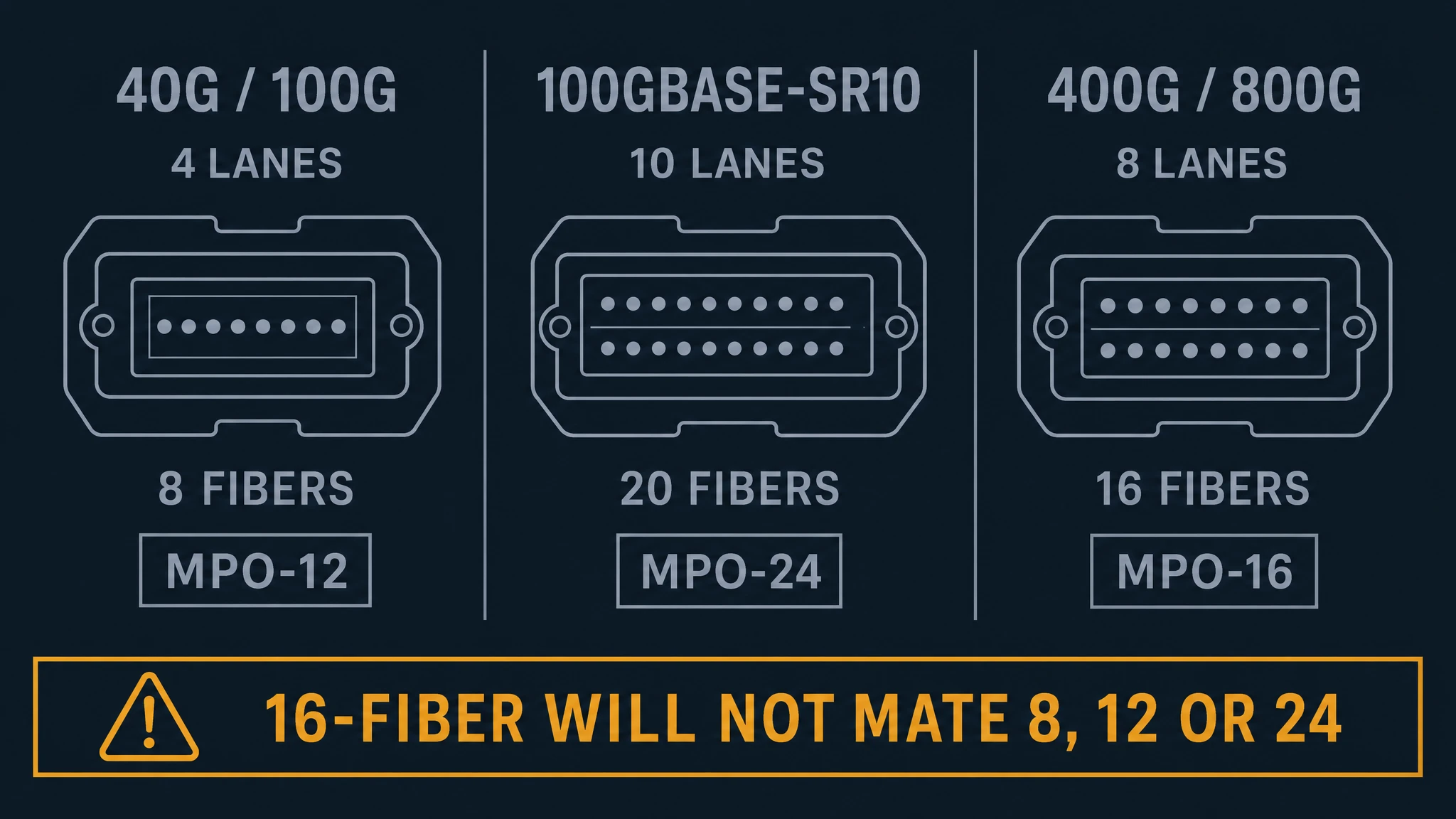
The trap sits between those counts, and it catches people because MPO arrays look interchangeable and are not. A 12-fiber MPO plug will physically seat in a 24-fiber adapter — the mating geometry allows it — and it will not mate properly. And the 16-fiber and 32-fiber arrays the 400G and 800G generations use cannot mate legacy 8, 12 and 24-fiber connectors at all: to fit the extra fibers between the guide pins, the pin holes move toward the edge of the ferrule, so the end faces cannot close. Connector manufacturers color-code boots and adapters by fiber count precisely because of this, which is documented in Leviton's MPO connector best-practice paper and worth adopting as a habit — read the count off the part, do not infer it from how the plug fits.
There is a second-order version of the same trap. Because arrays are not interchangeable across counts, the fiber count you install becomes a commitment. Build base-12 trunks today expecting 16-fiber optics later and you are planning a re-pull of the trunk, not a swap of patch cords. Build base-8 or base-16 today to serve eight-lane optics and a 20-fiber legacy application cannot ride the same trunk. Counting lanes first is cheaper than counting them afterwards.
Where the Connector's dB Sits in a Channel Budget
Connector loss figures are usually quoted in isolation — "low-loss MPO, ≤0.35 dB per mated pair" — and in isolation they tell you almost nothing, because a connector is one line item in a budget that also contains the fiber, the splices, the module and a margin.
TTI Fiber's own fiber dB loss calculator keeps those lines deliberately separate: it returns cable attenuation from a published dB/km matrix and states plainly that the result excludes connector pairs, fusion splices, splitters, transceiver tolerances and engineering margin. The companion link-budget tool adds them back as separate rows, and the practice maxima it applies are 0.75 dB per mated connector pair and 0.30 dB per fusion splice, labeled there as the TIA-568 recommended maximum. Those are the numbers to budget with, and they change the shape of this comparison.
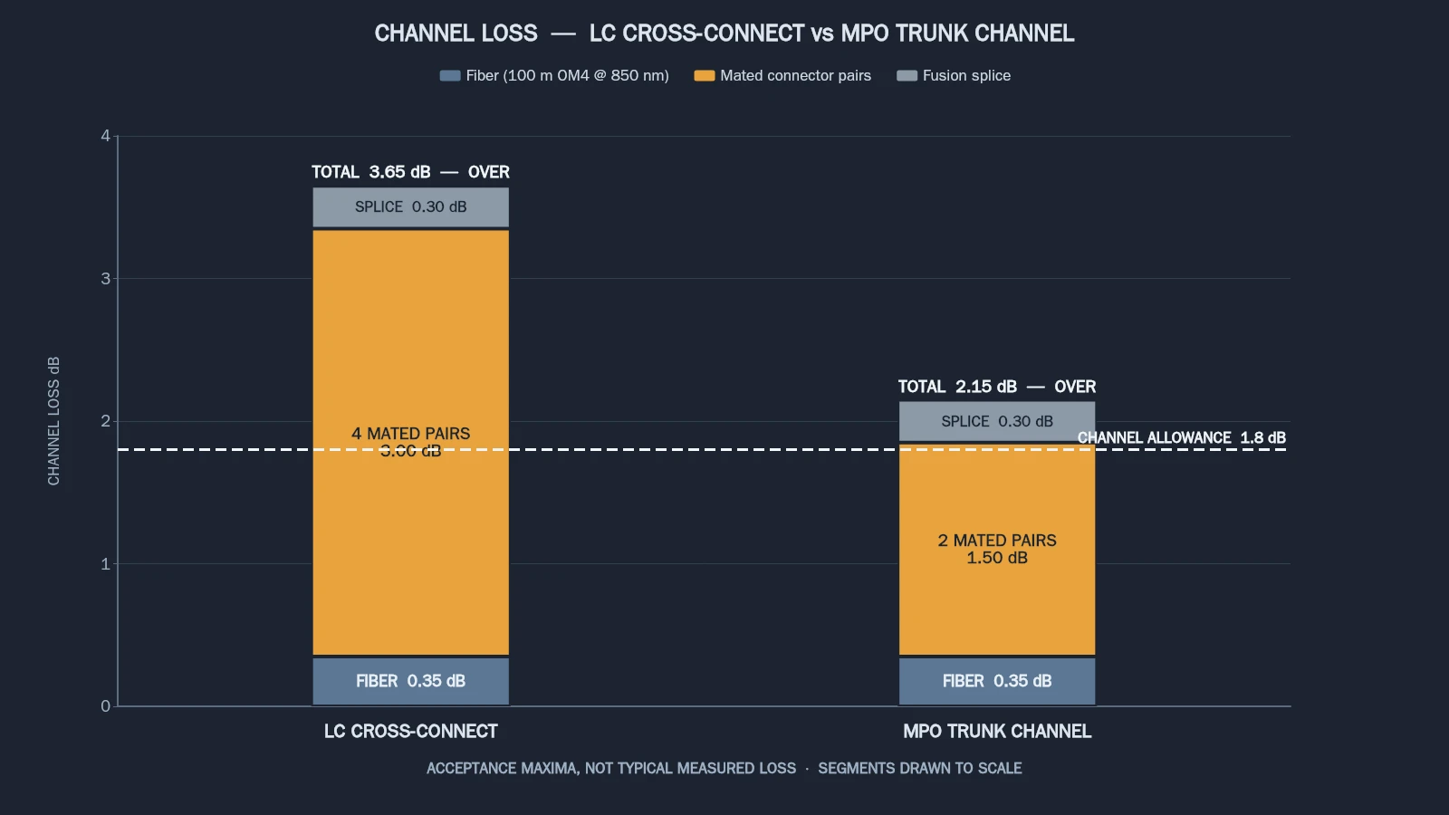
Now put them next to a real channel allowance. 800GBASE-SR8 over OM4 has a maximum channel insertion loss of 1.8 dB, and 400GBASE-SR4.2 has 1.8 dB on OM4 as well. At 0.75 dB per mated pair, two mated pairs consume 1.5 dB of a 1.8 dB allowance — leaving 0.3 dB for the entire fiber span, every splice in it, and any repair margin. A third mated pair in the path exceeds the allowance on paper before a single meter of fiber is counted. And a channel with two cross-connects passes four mated pairs, which on the same basis is 3.0 dB against an allowance of 1.8 dB.
Read that as an envelope rather than a prediction. The TIA-568 figures are the maxima you plan against and test against, not the loss you should expect from a well-made assembly; a measured MPO mated pair is normally well under it. What the envelope tells you is how many connector positions the channel is allowed to contain once you plan for the worst case — and that number, not the connector family, is what constrains the design.
The envelope has a sharp edge at the top of the reach, and it is worth seeing once. On the published after-cable matrix, 100 m of OM4 at 850 nm contributes about 0.35 dB of fiber loss. Add it to two mated pairs at the maximum and the channel sits at roughly 1.85 dB against an allowance of 1.8 dB. Maximum-for-maximum, a full-reach 800G multimode link does not fit with two connector positions in it — which is precisely why long parallel-optics channels are designed to minimize positions rather than to add them, and why the mated-pair count is the figure a reviewer should ask you for.
Three readings follow, and none of them is "MPO is better":
- The count of mated pairs in the path is the design lever, not the connector family. A cross-connect adds two positions; a second adds two more. That holds whether the positions are MPO or LC, and it is why the position count is the number to watch.
- A lower-loss array grade buys channels; it does not buy density. Where an allowance is tight, upgrading the connector's loss grade recovers a few tenths of a dB per position. No density claim comes with it.
- Return loss is a separate axis and cannot be traded against insertion loss. Multimode MPO assemblies are commonly flat-polished while single-mode MPO assemblies use angled end faces; LC exists in both physical-contact and 8° angled forms across the same adapter family. Angled and non-angled end faces must never be mated, and a reflective interface degrades a receiver even when the insertion-loss number looks healthy. What counts as a healthy loss figure per link is worth checking against what counts as a good dB loss before you sign an acceptance test.
The money follows the same lines. LC-side cost scales with adapter positions, patch cords and per-position field labor. MPO-side cost scales with ferrule grade, pin and housing hardware, and factory test time — because an array assembly is tested before it ships, and testing 12 or 24 fibers at once is a different cost structure from testing one. Neither is cheaper in the abstract; they are cheaper under different fiber counts.
Polarity, Mating and the Failures a Loss Test Will Not Catch
An LC duplex pair cannot really be plugged in wrong. The latch goes in, the pair arrives, and transmit meets receive or it does not. An MPO array can be wrong in several ways at once, and the failure is quiet: a channel with the wrong polarity passes insertion loss and carries no traffic.
The variables are the key and the routing. An MPO plug has a key on one side, and it can face up or down; the adapter can hold the two plugs key-to-key or key-to-keyway; and the cable itself is built to a scheme that straight-throughs, reverses or pair-swaps the fibers. TIA-568.3-D names three polarity methods — A, B and C — and the FOA's array reference sets out the cable and adapter variants that follow from them. The two that matter in practice, and the third that matters at breakouts, come down to this:
Method | Trunk cable | Patch cords | Where position 1 arrives | Why you would choose it |
|---|---|---|---|---|
Method A | Type A, straight-through: key up one end, key down the other | Type A at one end, reversing Type B at the other | position 1 | you inherit a Type A plant, or you want the fiber color code to run straight through the trunk |
Method B | Type B, reversing: key up at both ends | Type B at both ends | position 12 | the cords are identical at both ends, so there is no "which cord goes where" decision — which is why it is the method most often recommended |
Method C | Type C, adjacent pairs flipped: key up one end, key down the other | as required | position 2 for each pair | breakout to duplex at both ends; not for parallel optics that run whole arrays |
The cable-level detail, including the full position maps and the field-changeable connectors that let you flip polarity or gender on site, is covered in MPO polarity Type A vs Type B.
Mating has its own rule. MPO interfaces on active equipment are male — they carry the guide pins — so patch cords mating to them should be female, without pins, to avoid damaging the transceiver. The industry's own naming for this is "pins" and "no pins" rather than male and female, and the two conventions describe the same thing. The full set of options is genuinely large, and the FOA's treatment of testing cables with multi-fiber and array connectors is worth reading before your first plant, because it also explains why array testing is not a single-fiber test with a bigger adapter. Array instruments, end-face inspection and the temptation to treat a ribbon as 12 independent fibers are part of the platform's operating cost, and polarity planning belongs in the same document set that governs the rest of the plant — see the TIA-568 structured cabling standard.
Two habits cut most of this risk. Decide polarity once, in design, and put it in the drawing — order the trunk and the patch cords to that method and do not vary by row. Then test polarity explicitly, not just loss. The failure mode here is not a bad number on a meter; it is a channel that meets every threshold you set and still does not pass traffic.
When LC Is Still the Right Answer
LC is not the legacy side of a migration. It is the correct answer for a large share of the ports in a modern hall, and here is where it wins.
- Where the equipment port is a duplex port, there is no choice to make. SFP and SFP+ access ports, most server network cards, storage host bus adapters and out-of-band management ports are physically duplex. Whatever the trunk looks like, the last meter is duplex LC, and the remaining question is how you break the array out.
- Field test and repair scale better on LC. A single-fiber loss test set and single-fiber inspection are the cheapest instruments in the toolkit and the most widely available. Repairing a damaged LC ferrule is a single-fiber re-termination a technician can do on site; repairing a damaged MT ferrule means replacing an assembly terminated and tested in a factory. For a plant with modest fiber counts, that difference in mean time to repair dominates any density saving.
- Low fiber counts do not pay for the discipline. Polarity planning, an array test instrument and count discipline are real costs. Below a certain bundle size — a handful of duplex links between two racks — they buy nothing, because there was never a position problem to solve.
- Cordage handling is genuinely easier. A duplex cord routes, dresses and re-routes in a cabinet with a tolerance for being pulled around corners. A ribbon trunk terminating in a rigid multi-fiber ferrule is stiffer, has a defined minimum bend radius that must be respected at every turn, and punishes a tight radius with loss you will not see until the link is live. In dense, awkward, frequently changed rows that is a real advantage.
- Polish flexibility comes free in the LC family. The same adapter footprint carries physical-contact and 8° angled plugs, so a single-mode run can be angled at both ends without changing the front panel. MPO offers both too, but the combination must be specified per assembly, and the two polish types cannot be mixed.
And SC deserves the same courtesy. It is not in this comparison because modern duplex patch fields are not built on it, but a great deal of installed passive-optical plant still runs on it, and pretending otherwise would be a comparison designed to make one answer easy.
The Hybrid Patch Field: MPO at the Rear, LC at the Front
Put the two halves together and you get the architecture most high-density halls actually converge on: an MPO trunk that stops at a panel, and LC duplex ports on the front of that panel.
A pre-terminated MPO trunk runs from the main distribution area to the row, terminating on MPO adapters at the rear of a 1U panel. On the front, a cassette or breakout assembly presents duplex LC ports to the servers. The rear is where the position saving lives; the front is where the duplex reality lives.
There are two ways to build the front, and they differ in how they behave when the plant changes:
- Cassettes convert inside the housing. Order the cassette for the polarity method you chose and the conversion is fixed and repeatable — the same part number in every row, easy to label and document. The 12/24-port module with LC breakout, specified at ≤0.35 dB on the MPO side and ≤0.15 dB on the LC side, is the standard building block, and those are maker specifications rather than measured outcomes on your plant.
- Breakout assemblies — a plug-to-plug harness with MPO one end and LC connectors the other — give length flexibility and can be run straight to a rack with no panel in between. They are harder to label, easier to get wrong, and their polarity must match the trunk.
Pre-terminated assemblies dominate new builds for a reason that is not marketing: connector loss and end-face quality are decided in a factory with interferometers and automated polishing rather than at height on a ladder in a live hall. That moves the field work from polishing to plugging, the largest single lever on installation time and first-pass test results. The housing decision that follows is covered in choosing the patch panel.
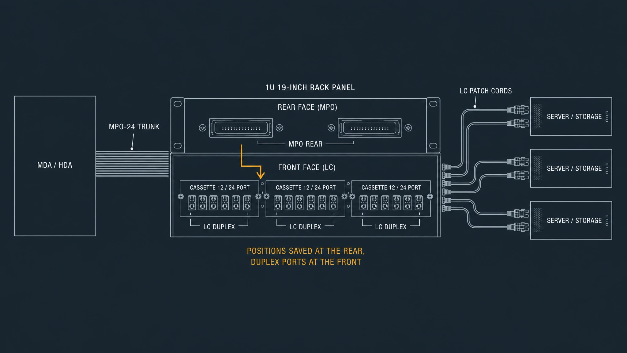
Two design notes for this architecture. Decide where polarity is flipped and write it down — inside a cassette the flip can live in the module, which is a gift as long as nobody mixes modules of different methods in one panel. And count the mated pairs across the whole channel, not within one component: a channel crossing this patch field passes through more positions than the datasheet for any single part suggests, and the budget arithmetic does not care which part is which.
How to Choose, by Link and by Patch Field
No single answer covers a hall. Route by link:
Situation | Rear (trunk / patch) | Front (equipment port) | Why |
|---|---|---|---|
New spine/leaf fabric, module ports are MPO | MPO-24 or MPO-16 trunk | MPO at the module | the optics port is the array; nothing to decide |
New fabric, server fleet is duplex LC | MPO trunk | cassette or breakout to LC duplex | one trunk, many duplex ports, positions saved at the rear |
Mixed 10G/25G access with 100G/400G uplinks | MPO for uplinks | LC duplex for access | access ports have no array option; uplinks have no duplex option |
Storage and SAN | LC, unless the HBA is an array | LC duplex | the HBA port decides, and most are duplex |
Small colocation cage, one or two racks | bonded duplex LC trunks | LC duplex | the position saving does not pay for polarity discipline and array test gear |
Existing 12-fiber installed base | keep 12-fiber | as installed | a 12-fiber plug does not mate a 24-fiber adapter properly |
400G or 800G uplinks on multimode | 16-fiber | MPO-16 | the lane count defines the fiber count; legacy counts cannot be reused |
Anything going through a standards review | depends | depends | ANSI/TIA-942-C, published 2024, is the data center infrastructure standard covering cabling and connectivity requirements — cite the revision, because an earlier one may not cover the connection types now in use |
Three checks, in order, will resolve most designs without a debate:
- Count the positions in the full channel. If the design already contains two cross-connects, the connector question is largely settled by the budget before any family is chosen.
- Count the lanes the optics demand. That gives the fiber count, which gives the array. Do not choose the array first and hope the optics fit.
- Ask what the last meter looks like. If it is duplex, the patch field is LC at the front, and MPO vs LC becomes an argument about the trunk rather than about the patch field.
FAQ
Is MPO the same as MTP? No, and the difference is ownership rather than geometry. MPO is the standardized multi-fiber connector interface. MTP is a registered trademark of US Conec for its own MPO-format connector. Both follow the same interface standards, so an MTP connector mates with a compliant MPO connector in the same adapter. "All MTP are MPO; not all MPO are MTP" is the usual summary, and the procurement consequence is that the mark is licensed rather than open.
Can I plug a 12-fiber MPO into a 24-fiber adapter? It will go in, and it will not work. The body geometry allows the mating; the fiber positions do not line up as the connection implies. This is why connector makers color-code boots and adapters by fiber count, and why reading the count off the part beats inferring it from how the plug fits.
What is the difference between an SFP and an MPO connector? They are different kinds of thing, which is why the question keeps coming up. An SFP is a transceiver module form factor — a pluggable package holding the optics and presenting an electrical interface to the switch. MPO is a connector interface on the optical side. A module's optical port can be duplex LC or a multi-fiber array depending on the application, so "SFP versus MPO" compares a module with a connector, not two connectors.
Does higher density mean lower loss? No. Density is a position count; loss is a budget line. A channel's connector contribution is the number of mated pairs in the path multiplied by the loss per pair, and the count of pairs — not the connector family — is usually what pushes a channel over. Where an allowance is tight, a lower-loss grade recovers a fraction of a dB per position; it does not make the positions disappear.
Can I standardize on MPO and still have LC at the front? Yes, and in most halls that is the answer. Terminate the trunk on MPO at the rear of the panel and present duplex LC on the front through cassettes or breakout assemblies.
Do I need a different tester for an MPO plant? Yes. A single-fiber loss test set does not transfer to array connectors, and array testing brings its own instrument class, reference-cord discipline and end-face inspection practice, because one measurement now covers 8, 12 or 24 fibers. Budget for it before the first plant rather than after the first failed acceptance test.
Is LC vs APC a real comparison? No — it is a terminology collision, not a design choice. LC is a connector family; APC is an end-face polish with an 8° angle, available on LC plugs. So "LC vs APC" is really "LC versus an LC with a different end face", and the rule that always applies is that an angled end face must never be mated to a flat one.
What to Do Next
If you take one sentence from this comparison, take the position count: MPO puts 24 fibers on one connector position and LC gives every pair its own — a twelve-to-one difference in adapter positions, patch cords and inspection events, and a twelve-to-one difference in how many channels one contaminated ferrule takes down. Density is what that ratio buys; loss, polarity and repair are what it costs. The judgment is which of those properties each link in your design actually needs.
Do two counts before you order anything. Count the mated pairs the full channel will pass through and check them against the module's channel allowance. Count the lanes the optics demand and check them against the arrays you are about to install, including the ones already in the floor. Both counts are arithmetic, and both are cheaper than a re-pull.
The rest of the data center cabling material — 400G and 800G optics, fiber counts, polarity, panel choices and the fiber grades underneath them — sits under Data Center Fiber Cabling, alongside this article.