Fiber DB loss calculator — Free Online CalculatorTurn distance into loss—or loss into distance.
Estimate attenuation from the documented maximum dB/km values for common single-mode and multimode fibers. Choose a fiber, wavelength, and specification basis—before or after cable construction—then calculate in either direction without mixing connector, splice, or system margin.
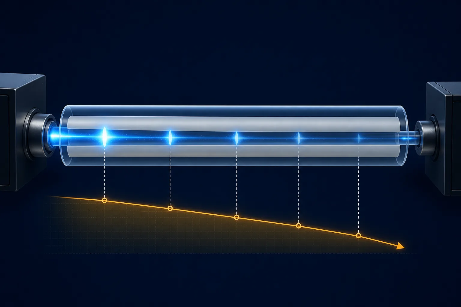
Fiber attenuation and distance calculator
Single-mode · Standard low-water-peak single-mode fiber
Fixed to the Word specification maximum for OS2 · G.652D, before cable, at 1310 nm.
Calculated result
3.4
dB fiber loss
10 km × 0.34 dB/km
= 3.4 dB
Before cable reference. This result excludes connectors, splices, splitters, equipment tolerances, and engineering margin.
Keep the result moving
Fiber DB Loss Calculator, with a useful next step.
A fiber DB loss calculator estimates attenuation from cable distance and the maximum dB/km value in a fiber specification. The coefficient depends on fiber family, operating wavelength, and whether the specification is measured before or after cable construction. This tool includes the TTI Fiber references for OM1, OM2+, OM3, OM4, OM5, OS2 G.652D, G.657A1, G.657A2, and G.655 across the documented wavelengths. Use Distance → loss when planning a cable run, checking a measured span, or estimating the loss for a selected specification basis. Use Loss → distance when a receiver or system budget gives you a maximum loss allowance. The result excludes connector pairs, fusion splices, splitters, transceiver tolerances, and engineering margin; those items belong in a complete link loss budget. Select only the documented wavelength for the chosen fiber, and verify the fixed planning value against the exact product datasheet before purchasing or acceptance testing.
Related reading and products
Explore the product options and technical background behind this result.
A quick planning estimate,not a complete link budget.
- 01Select the fiber class, specification basis, and operating wavelength.
- 02Use the fixed documented maximum attenuation for the selected fiber, wavelength, and cable basis.
- 03Enter distance for expected loss, or enter the loss allowance for maximum distance.
For purchasing or acceptance testing, use the exact cable specification and add all passive components plus an engineering margin in the full link loss budget calculator.
Wavelength reference matrix
Attenuation by fiber and wavelength
| Fiber | Core / cladding | Wavelength | Before cable | After cable |
|---|---|---|---|---|
| OS2 · G.652D | 9/125 µm | 1310 nmCatalog reference | 0.34 dB/km | 0.35 dB/km |
| 1383 nmCatalog reference | 0.34 dB/km | 0.35 dB/km | ||
| 1550 nmCatalog reference | 0.20 dB/km | 0.22 dB/km | ||
| 1625 nmCatalog reference | 0.24 dB/km | 0.25 dB/km | ||
| G.655 | 9/125 µm | 1550 nmCatalog reference | 0.21 dB/km | 0.22 dB/km |
| 1625 nmCatalog reference | 0.20 dB/km | 0.21 dB/km | ||
| G.657.A1 | 9/125 µm | 1310 nmCatalog reference | 0.35 dB/km | 0.36 dB/km |
| 1383 nmCatalog reference | 0.35 dB/km | 0.36 dB/km | ||
| 1550 nmCatalog reference | 0.21 dB/km | 0.24 dB/km | ||
| 1625 nmCatalog reference | 0.23 dB/km | 0.25 dB/km | ||
| G.657.A2 | 9/125 µm | 1310 nmCatalog reference | 0.35 dB/km | 0.36 dB/km |
| 1383 nmCatalog reference | 0.35 dB/km | 0.36 dB/km | ||
| 1550 nmCatalog reference | 0.21 dB/km | 0.24 dB/km | ||
| 1625 nmCatalog reference | 0.23 dB/km | 0.25 dB/km | ||
| OM1 | 62.5/125 µm | 850 nmCatalog reference | 2.70 dB/km | 3.50 dB/km |
| 1300 nmCatalog reference | 0.60 dB/km | 1.50 dB/km | ||
| OM2+ | 50/125 µm | 850 nmCatalog reference | 2.40 dB/km | 3.50 dB/km |
| 1300 nmCatalog reference | 0.60 dB/km | 1.50 dB/km | ||
| OM3 | 50/125 µm | 850 nmCatalog reference | 2.40 dB/km | 3.50 dB/km |
| 1300 nmCatalog reference | 0.60 dB/km | 1.50 dB/km | ||
| OM4 | 50/125 µm | 850 nmCatalog reference | 2.40 dB/km | 3.50 dB/km |
| 1300 nmCatalog reference | 0.60 dB/km | 1.50 dB/km | ||
| OM5 | 50/125 µm | 850 nmCatalog reference | 2.40 dB/km | 3.50 dB/km |
| 1300 nmCatalog reference | 0.60 dB/km | 1.50 dB/km |
Blue values are the fixed documented maximum attenuation references. Choose the matching before-cable or after-cable basis in the calculator. Actual attenuation varies by product, installation, temperature, and test method.