800G OSFP Fiber for AI Cluster Fabrics
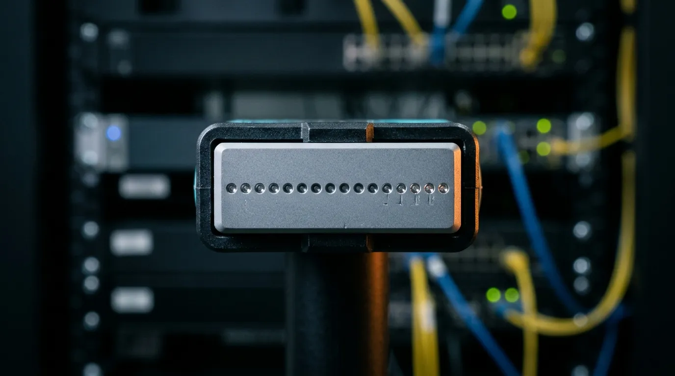
An OSFP 800G port looks like two 400G ports bolted together. On the bill of materials it almost is: the same 100 Gb/s electrical lane, the same PAM4 signaling, twice the lane count. On the floor it is not, because every eight-lane parallel 800G port you deploy commits sixteen fibers and a channel budget that the standard publishes and no module page mentions.
That gap is where AI cluster builds lose weeks. The optics are decided early and by someone else — the switch vendor certifies a short list, the reach picks the family, and OSFP or QSFP-DD falls out of the platform. The cable plant is the part still open when the purchase order is written, and it is the part that decides whether the ports come up at 800G, at 400G, or not at all.
The 800G port is the design problem, not the 800G module
The governing document is IEEE Std 802.3df-2024, approved in February 2024, which added 800 Gb/s MAC parameters and the 800G physical layers on top of the 400G work. Its 800G PMDs are eight-lane, 100 Gb/s-per-lane designs: 106.25 Gb/s of line rate per lane, carried as 53.125 GBd PAM4, with forward error correction handled by the host rather than the module.
Eight transmit lanes and eight receive lanes means sixteen fibers per port. Not sixteen per two ports, not sixteen shared with a neighbour. One 800G DR8 port consumes an entire 16-fiber trunk.
At AI fabric density that number stops being abstract. NVIDIA's Quantum-X800 switch carries 144 ports of 800 Gb/s in one chassis, and its ConnectX-8 SuperNIC is rated at up to 1.6 Tb/s of connectivity per GPU, which is two 800G ports per GPU. Run the arithmetic: 144 ports times 16 fibers is 2,304 fibers leaving a single switch, and 72 GPUs at two ports each is another 2,304 fibers leaving a rack. A 400G generation with 8-fiber ports would have needed half of that for the same port count, and an eighth of it — a quarter of the 8-fiber case — if the design used duplex single-mode.

Two rows of switches, one aisle of trunk. At 800G every port in this frame is worth sixteen fibers.
This is the layer the data center fiber cabling hub covers end to end: media, connector counts, polarity, and the loss margin that decides whether a channel trains. The 800G generation changes the numbers in all four.
What an OSFP 800G port costs in fiber
Four 802.3df PMDs do the work in a data center, and the differences that matter are not the ones in the marketing table. Fiber count, maximum channel insertion loss, and the connector interface decide the plant; reach only decides which row you are in.
PMD | Media | Fibers per port | Reach | Max channel insertion loss |
|---|---|---|---|---|
800GBASE-DR8 | OS2 single-mode | 16 | 500 m | 3.0 dB |
800GBASE-DR8-2 | OS2 single-mode | 16 | 2 km | 4.0 dB |
800GBASE-SR8 | OM4 / OM5 multimode | 16 | 100 m on OM4 (60 m on OM3) | 1.8 dB on OM4/OM5, 1.7 dB on OM3 |
800GBASE-VR8 | OM4 / OM5 multimode | 16 | 50 m on OM4/OM5 (30 m on OM3) | 1.7 dB on OM4/OM5, 1.6 dB on OM3 |
800G 2×FR4 (OSFP MSA implementation) | OS2 single-mode | 4 | 2 km | vendor-specified per 400G-FR4 |
800G 2×DR4 (OSFP MSA implementation) | OS2 single-mode | 16 (8 lit in each of two MPO-12) | 500 m | vendor-specified per 400G-DR4 |
800GBASE-CR8 | Twinax copper | n/a | 2 m | n/a |
Sources for the DR8-2 and VR8 rows: 800GBASE-DR8-2, 2 km · 800GBASE-VR8, 50 m.
The loss figures are the point. They come from the same standard pages that give the reach, and they are the numbers a design either passes or does not. The 800GBASE-DR8 channel characteristics allow 3.0 dB of insertion loss across a 500 m channel; 800GBASE-SR8 allows 1.8 dB over 100 m of OM4. The 2 km DR8-2 row allows 4.0 dB and the 50 m VR8 row 1.7 dB. Read the multimode rows twice: 1.8 dB is about what four clean mated MPO pairs cost, with the 100 m of glass coming out of the same allowance as a rounding error.
Two entries in that table are not IEEE PMDs, and the distinction is not pedantry. 800G 2×FR4 and 800G 2×DR4 are dual-400G modules built inside the OSFP form factor: two independent 400G PHYs sharing one cage. They interoperate as 400G links, they are managed and alarmed as two 400G links, and a fault in one half leaves the other half running. A vendor datasheet makes the split explicit: the 2×400G-FR4 module carries four wavelengths per fiber over two duplex LC pairs, 2 km, and its optical connector is UPC duplex LC rather than an MPO at all.
That single alternative — four fibers instead of sixteen — is the largest lever in the table, and it is worth understanding before the connector discussion.
If the design is still on the 400G side of the line, the decision order and the base-8/base-16 collision are already covered in the 400G fiber cabling guide; this article picks up at the point where 100 Gb/s per lane changes the constraints.
The cage choice between OSFP and QSFP-DD800 looks like a module question and behaves like a plant question. Both form factors carry eight lanes, so either one lands on the same sixteen-fiber, APC-terminated channel and neither makes the cabling cheaper. What differs is mechanical: OSFP's taller body and deeper heat sink set how much clearance the first 200 mm of cable has above the cage, and that clearance decides whether a bend-radius specification is achievable in a full line card. The management side has the same shape. CMIS, the module management interface, is what tells the platform which lane widths and breakouts the module can present, so the cage choice and the breakout plan are linked by firmware as well as by glass.
8x100G, 4x200G, 2x400G: breakout changes the failure domain, not the strand count
Every 800G module in the table breaks out, and the arithmetic surprises people who assume a breakout reduces fiber. It does not. One 800G cage split eight ways lights the same sixteen fibers as one 800G link:
- 8 × 100G — eight links, two fibers each, sixteen fibers total.
- 4 × 200G — four links, four fibers each, sixteen fibers total.
- 2 × 400G — two links, eight fibers each, sixteen fibers total.
What changes is everything else. The number of downstream ports you serve goes from one to eight. The number of connectors and mating points goes up with every split, and every mating point spends loss from the same fixed budget. And the failure domain inverts: in 800G mode one port is one link, while in 8×100G mode one port is eight links that fail independently.
That last difference is the one fabric designers actually design around. A single contaminated position, a single high-loss lane, a single length mismatch among the sixteen fibers is enough to hold an 800G port down — the whole port, not one eighth of it. The same defect in a broken-out configuration costs one 100G link and leaves the other seven running. Back-end GPU-to-GPU fabrics, where every link matters equally and training jobs synchronize across all of them, tend to stay at 800G and get the cleanest plant. Front-end and storage fabrics, where a single degraded link is absorbed by the application, are where breakout pays: an 800G module amortized across eight 100G ports is the cheapest way to buy 100G at the edge of a cluster.
There is also a connector-granularity cost that never appears in the cost-per-100G table. A 4 × 200G breakout built on 12-position MPO trunks leaves four positions dark per MPO-12 trunk; an 8 × 100G breakout built on a single 16-position trunk needs an eight-way harness at the far end and eight duplex LC connections in the panel. Each of those is a mate you will inspect and a loss you will budget. The density trade-offs between multi-fiber trunks and duplex LC at the panel are covered in MPO vs LC in high-density cabling; at 800G the question is not which is denser but where you want the matings to sit.
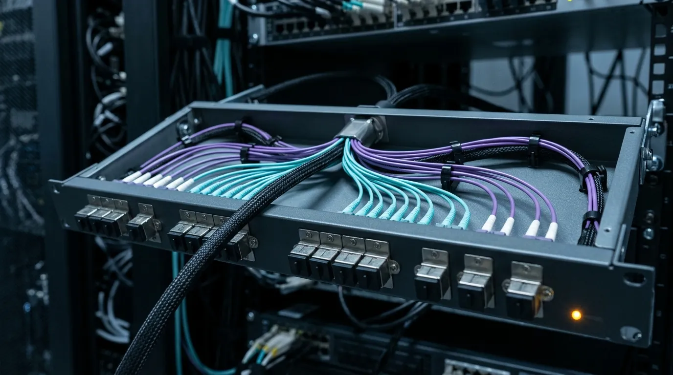
Breakout happens at the panel, not in the cloud: one 16-fiber trunk arriving, eight duplex pairs leaving, eight chances to lose a lane.
100G per lane: the margins that stopped being generous
A 100 Gb/s lane is not a fast version of a 25 Gb/s lane; it is a different optical budget problem. At 53.125 GBd PAM4 there are four amplitude levels per symbol, so the decision thresholds sit three times closer together than in NRZ, and the receiver depends on forward error correction to recover what the channel smears. Module datasheets are explicit that the FEC is performed on the host platform, not inside the optic, which means the channel's job is to deliver a signal clean enough that the host's FEC has something to work with.
Three plant properties feed directly into that:
Insertion loss per lane. In an 8-fiber-per-direction design, each of the sixteen fibers is its own optical path with its own connector positions. A channel that measures 2.4 dB "on average" can hide a 3.4 dB lane. Test per position, not per cable.
Return loss and polish. At 800G the parallel MPO interfaces are APC: the vendor datasheets for both the multimode VR8 and the single-mode DR8 require angled-physical-contact MPO patch cords, which is a change from the 40G/100G era when multimode meant UPC as a matter of habit. (The duplex-LC variants are the exception — 2×FR4 takes UPC LC.) An APC port mated to a UPC cord does not fail cleanly; it produces a reflective, unstable link that may still come up and then drop under load.
Cabling skew. The 802.3df multimode channels — the SR8 and VR8 rows linked above — specify a maximum cabling skew of 79 ns across the sixteen fibers, with 2.4 ns of allowed variation. That limit exists because the host deskews the lanes, and the deskew buffer is finite. A channel assembled from a 30 m trunk and a 90 m trunk, or from two harnesses built in different batches to different length tolerances, spends that budget before it spends any loss. No insertion-loss test will ever show it.
The channel did not get slower. It got less forgiving: the same 0.2 dB of dirt that cost a 400G port five percent of its margin can cost an 800G port the link.
That asymmetry is why the per-lane view matters more than the port view. On a 400G SR8 port with eight 50 Gb/s lanes, a marginal lane degrades the link. On an 800G port with eight lanes at twice the per-lane rate, a marginal lane can hold the entire port at a lower width or keep it from coming up — and the operator sees "port down", not "lane 6 dirty".
The 3.0 dB budget, itemized
The standard does the arithmetic for you and then hides it in a footnote. For 800GBASE-DR8 the 500 m reach is calculated with a 2.75 dB allocation for connections and splices, inside a 3.0 dB total channel loss. Put the fiber loss next to it: OS2 attenuates at 0.4 dB/km, so 500 m of glass costs 0.2 dB. The whole channel comes to 2.95 dB against a 3.0 dB limit, and the fiber is almost free. Connections are the design.
Channel | Max insertion loss | Fiber loss | For connections and splices | Mated pairs at 0.35 dB |
|---|---|---|---|---|
DR8, 500 m OS2 | 3.0 dB | 0.20 dB | 2.75 dB (the standard's allocation) | 7 |
DR8-2, 2 km OS2 | 4.0 dB | 0.80 dB | 3.00 dB (the standard's allocation) | 8 |
SR8, 100 m OM4 | 1.8 dB | 0.35 dB | 1.45 dB (residual, no allocation published) | 4 |
VR8, 50 m OM4 | 1.7 dB | 0.18 dB | 1.52 dB (residual, no allocation published) | 4 |
Seven pairs is the DR8 answer once the standard's own allocation is respected, and the arithmetic is unforgiving: 0.20 dB of fiber plus 2.75 dB of connection and splice loss is 2.95 dB, five hundredths of a decibel inside a 3.0 dB limit, and 2.75 dB buys seven mated pairs at 0.35 dB with 0.30 dB left over for the splice allocation.
The multimode rows are the ones that catch people. Multimode is where the budget disappears. A 100 m OM4 channel at 850 nm carries about 3.5 dB/km of attenuation, which is 0.35 dB of fiber, leaving roughly 1.45 dB for every connector on the path. At a design value of 0.35 dB per mated MPO pair that is four pairs and five hundredths of a decibel of slack. Put a trunk through two patch panels with a cassette at each end and you are at the limit before the last patch cord goes in.
The 0.35 dB figure is a specification, not a hope. Published planning guidance puts multimode connectors in the 0.2–0.5 dB range typically, with a TIA-568 maximum acceptable connection loss of 0.75 dB per mated pair — and the loss-budget method itself is explicit that the worst-case values, not the typical ones, are what a pass/fail test should be written against for pre-terminated and MPO hardware. Designing an 800G SR8 channel against 0.75 dB per pair produces a channel that fails on paper; designing against 0.35 dB and testing against 0.75 dB produces one that passes inspection and fails in service.
Two practical consequences. First, single-mode at 500 m is the generous channel in this generation and multimode is the tight one, which is the reverse of the intuition most 10G-era engineers carry. Second, the number of panels between the two modules is now a design decision with a decibel price, not an installation detail. If the rack elevation calls for a cross-connect, the budget has to be re-run with the cross-connect in it — and if a channel lands at 1.5 dB of loss instead of 0.9 dB, that is information, not bad luck.
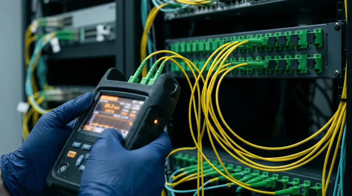
The budget is a hypothesis until a meter confirms it, per position, at the wavelength the optic actually uses.
For the general question of what counts as a good loss number on any fiber link, this explainer on dB loss in fiber optics covers the method; the 800G-specific point is that the acceptable number is now set by a 100 Gb/s lane and a fixed FEC budget rather than by a comfortable engineering margin.
MPO-16 or dual MPO-12: one PMD, two plants
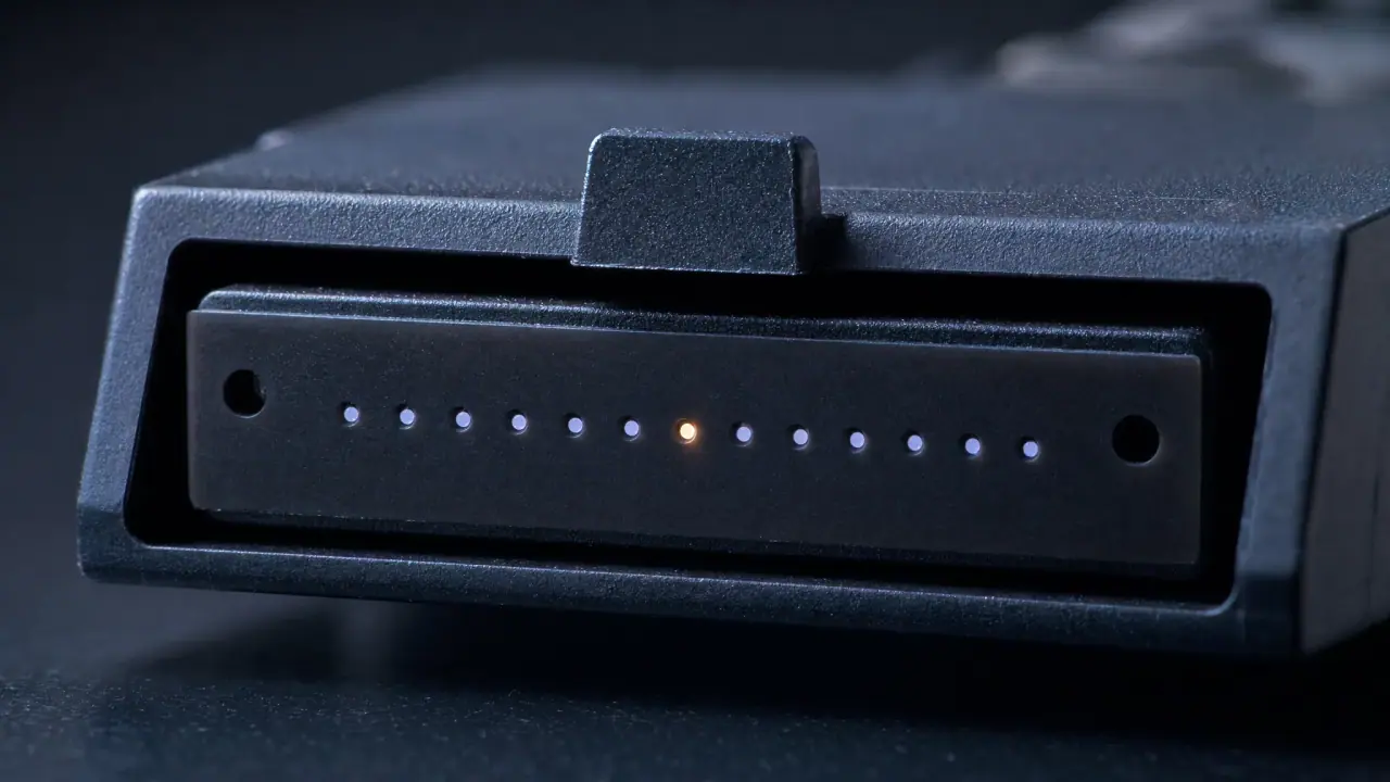
Here is the detail that makes 800G cabling harder than it looks. The same 800GBASE-DR8 PMD ships with two different optical interfaces, and both are current products. One module presents a single 16-position MPO; the other presents two 12-position MPOs with eight positions lit in each. Same PMD, same 500 m, same 3.0 dB, same 14.2 W typical draw and 16 W ceiling (17 W with diagnostics enabled). Different plant.
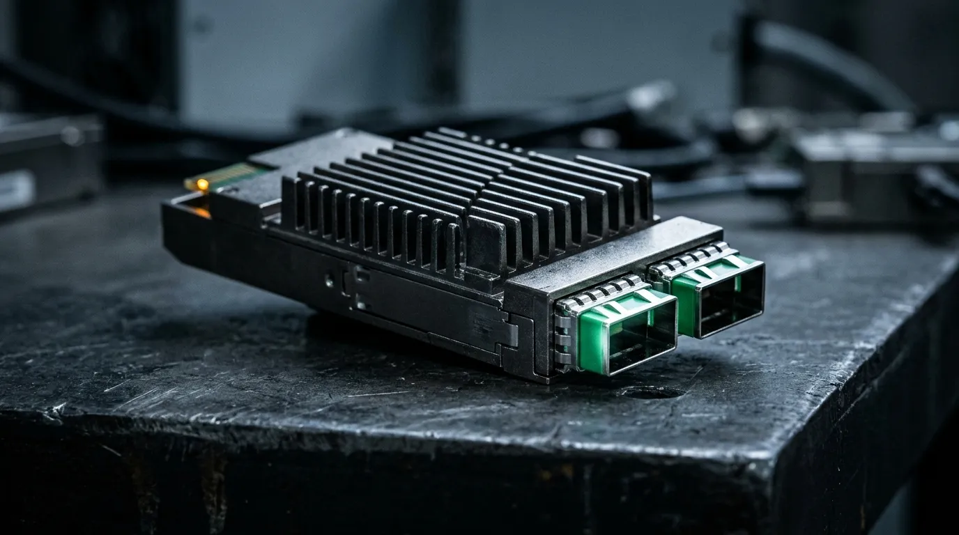
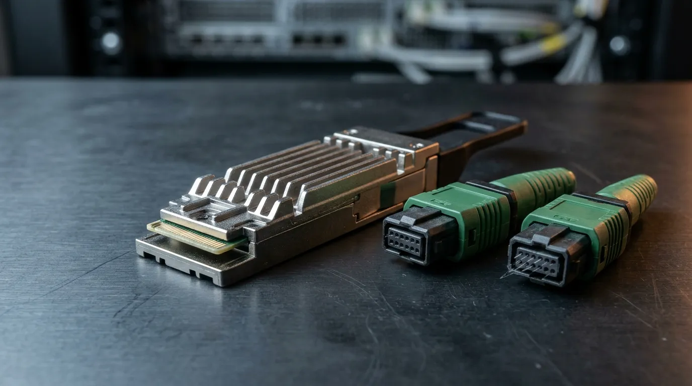
Two MPO ports on this variant — the dual-MPO-12 build of the same 800GBASE-DR8 PMD. Behind them: eight transmit lanes and eight receive lanes.
The 16-position interface is the cleaner engineering answer. Sixteen fibers in one ferrule, one mating point per end, a trunk that maps one-to-one onto the port, and a channel that spends two matings instead of four. For a new build it also simplifies documentation: one port, one trunk, one position map.
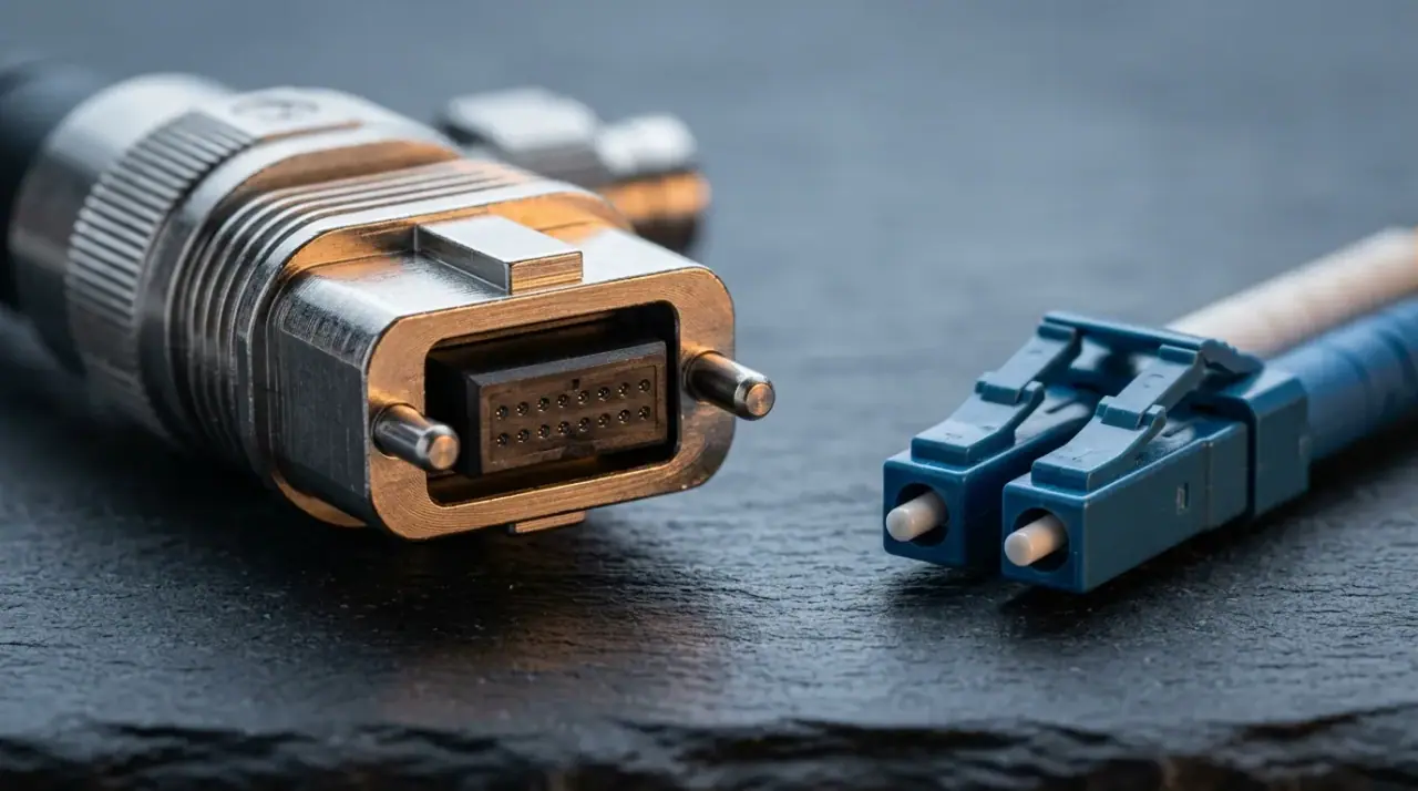
The dual 12-position interface is the migration answer. It rides the base-8 and base-12 infrastructure a 40G/100G plant already owns, it breaks out to 2 × 400G-DR4 without a harness, and it lets a 800G port land on panels that were specified years ago. The cost is structural: eight of twenty-four positions are dark, and every end-to-end channel carries twice the matings. At 0.35 dB per pair, that is roughly 0.7 dB, or a quarter of the DR8 connection allowance, spent on compatibility.
Neither is wrong. The mistake is mixing them inside one channel or ordering 16-position trunks for a 12-position panel because the module part number looked right. Position counts, polarity and the difference between the connector families are covered in the MPO-12, MPO-16 and MPO-24 position counts.
Then there is the part that decides whether a correctly specified channel works. Module MPO ports are male, also called pinned, and they accept only female, unpinned cords. A pinned-to-pinned mating does not produce a bad link; it produces two damaged ferrules and a spring-loaded connector that no longer seats. And because the 16-fiber mapping fixes which positions transmit and which receive, the polarity method has to be consistent from the module to the far end — the three methods and their failure modes are set out in MPO polarity Type A, B and C. A channel built with the wrong method tests clean end to end and receives nothing.
Sixteen-fiber APC trunks and harnesses are built-to-order items, not catalogue SKUs: the position map, the key orientation, the polish and the length tolerance belong on the drawing. That is the part of an 800G order where a supplier's process, rather than its price list, decides the outcome.
What an AI fabric does to the cabling plan
An AI cluster is not a leaf-spine network with bigger pipes. The dominant topology is rail-aligned: each GPU's network ports are distributed across different leaf switches, so that a collective operation such as an all-reduce flows over every rail at once and a single congested or failed leaf degrades the job instead of stopping it. That design has direct cabling consequences, and none of them are about optics.
Runs are parallel and must be similar. Rail-aligned fabrics produce large numbers of near-equal-length runs between the same two rows. That is good for loss consistency and bad for improvisation: a channel assembled from whatever trunk was left on the reel can violate the skew limit even when every individual assembly passes its own test.
Density lands on the panel, not the switch. A 144-port 800G switch is 144 trunks, and a rack of 72 GPUs at two 800G ports each is another 144. Pre-terminated trunk plus cassette is the only practical way to build at that count, which makes the cassette a performance component: every cassette adds two mated pairs to every lane of every channel that passes through it.
Front-end and back-end are different plants. The back-end fabric carries GPU-to-GPU traffic and is usually 800G end to end. The front-end carries storage, management and ingress, tolerates a lost link, and is where breakout to 100G or 200G makes economic sense. Specifying one cable type for both is how projects end up over-budget on the front-end and under-margined on the back-end.
Administration is not optional. At 2,304 fibers per switch, an undocumented position map is an outage waiting for the first maintenance window. The structured-cabling discipline that governs this — records, labeling, administration classes — is the same one described in how TIA-568 handles cable administration; the density is what changed, not the principle.
Where coherent 800ZR and 800LR replace the parallel plant
Parallel optics are the right answer inside a hall and a poor one between buildings. The escape hatch is coherent, and OIF's 800G coherent project has produced two implementation agreements for it. 800ZR (OIF-800ZR-01.0, October 2024) defines the single-wavelength 800G coherent interface for amplified single-span DWDM links of 80–120 km. Its 800LR companion (OIF-800LR-01.0, April 2025) covers the unamplified, fixed-wavelength link up to 10 km. Both carry Ethernet clients up to 800G aggregate.
The plant consequence is the same in both cases, and it is brutal and welcome: two fibers instead of sixteen. A campus or cross-building run is the 800LR case; a metro DCI between data centers, or a storage replication path between halls, is 800ZR. Coherent 800G removes seven eighths of the glass and all of the parallel-lane skew question; wherever the trench or the duct is the constraint, that is the whole trade. What it does not remove is the cost: a coherent DSP, tighter wavelength planning and higher power per port. For a 50 m leaf-spine link inside a hall, parallel optics win on power and price and will keep winning.
Between the two sits 800G 2×FR4: four fibers, 2 km, duplex LC, four wavelengths per fiber. It is the option that halves the fiber count twice over relative to DR8 without asking for coherent DSP, which makes it the natural choice for row-to-row links at the edge of the 500 m window. Whether the media on either end can carry it is a separate question, covered in choosing between OS2, OM4 and OM5 — at 2 km, it is OS2 and nothing else.
Specifying and qualifying an 800G channel
Everything above collapses into a purchase specification and an acceptance test. Six items belong in the RFQ, and leaving any of them to the supplier's discretion is how a channel ends up 0.4 dB over budget with no one to blame.
- The PMD by name, with the optical interface written out:
800GBASE-DR8, MPO-16 APCis a different line item from800GBASE-DR8, dual MPO-12 APC. Add the position map and key orientation for each assembly. - Fiber class and grade, not just "single-mode": OS2 to G.652.D for DR8, OM4 or OM5 with a stated minimum effective modal bandwidth for SR8 and VR8.
- Insertion loss per mated pair, specified at 0.35 dB maximum for APC MPO rather than the 0.75 dB TIA-568 ceiling, because the channel budget in this generation cannot absorb worst-case connectors.
- Return loss, specified separately from insertion loss and separately for APC and UPC interfaces. At 800G, the polish is part of the interface definition.
- Skew, expressed as a maximum length difference across the fibers within one channel, not as a per-assembly tolerance.
- Test data per assembly and per position, at the operating wavelength, with the reference method stated: which cord, which launch condition, which meter.
The acceptance test has four parts, and the first two are the ones that get skipped.
Per-position loss on all sixteen fibers. A 16-fiber trunk tested as a single "channel loss" number hides the one position that matters. Measure each position at 1310 nm for DR8 or 850 nm for SR8/VR8, with reference cords that match the polish. The method and the instrumentation are the same ones used for any link certification; OTDR testing adds the ability to locate a bad position rather than just flag it.
End-face inspection on 100% of positions. Sixteen positions in one ferrule means sixteen chances for a particle, and a scope image that shows "mostly clean" is a fail. Grade against the defect criteria the inspection standard defines (IEC 61300-3-35 is what most scopes implement), record the image per connector, and re-inspect after every re-mate.
Return loss on APC interfaces. This is where a UPC cord in an APC port shows up, and where a scratched ferrule shows up before it becomes an intermittent link.
A live link check with the optics installed. Loss and inspection prove the passive channel; they do not prove the channel plus the module. Bring the link up, read the pre-FEC bit error rate and the per-lane error distribution from the module's diagnostics, and compare against a known-good link in the same fabric. A channel that passes at 1.4 dB and shows elevated pre-FEC errors on one lane is telling you about skew or a marginal ferrule, not about loss.
Assembly-level test data — every position, every connector, tied to a serial number — is the difference between a supplier who can answer a commissioning question and one who cannot. It is also the only way to prove, six months later, that a channel that has drifted was built correctly and disturbed afterwards.
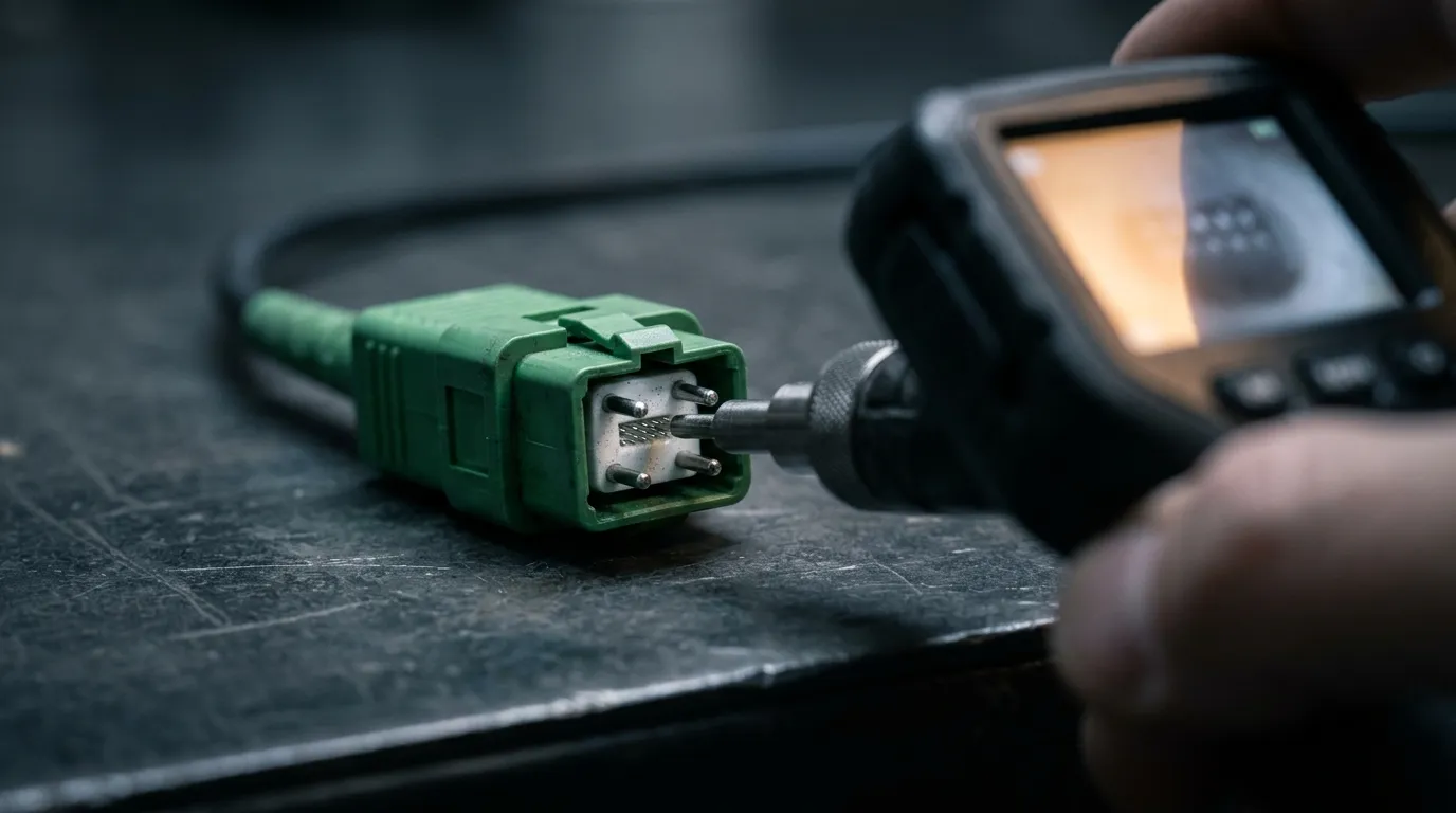
Sixteen positions, sixteen verdicts. Inspection is per position or it is decoration.
Build the plant for 1.6T while you are buying 800G
The next generation is already in committee. IEEE P802.3dj is defining 200 Gb/s, 400 Gb/s, 800 Gb/s and 1.6 Tb/s Ethernet on 200 Gb/s lanes, which doubles the per-lane rate again and doubles the port bandwidth for the same lane count. What it does not do is change the geometry: a 1.6T eight-lane PMD still needs sixteen fibers, and still lands on a 16-position MPO with APC polish.
That is the one piece of future-proofing worth paying for now. A 16-fiber APC trunk installed for 800G is the trunk that carries 1.6T; the optics at each end change, the glass, the panels and the documentation do not. A plant built on dual 12-position interfaces will need re-engineering at the next generation, because the lane count doubles while the position count per connector does not.
So the specification that survives both generations is short: 16-fiber APC trunks and harnesses, MPO-16 interfaces wherever the platform allows them, a documented position map per channel, per-position loss and inspection records, and enough margin in the budget that the channel is not sitting at 2.95 dB of a 3.0 dB limit on the day it is commissioned.
TTI Fiber builds MPO/APC single-mode trunks in 12, 24, 48 and 72 fibers to a documented mapping and a stated polarity, with a factory insertion-loss test report against each assembly — and 16-fiber assemblies to the same drawing as a built-to-order item on the same line. Those are the artifacts this article says to ask for. If you are specifying an 800G fabric and want the channel arithmetic checked against your rack elevations before the order goes out, send the design over and we will run the budget with you.