400G Fiber Cabling: Design Before You Buy

Every 400G fiber cabling project starts with the same conversation, and it starts in the wrong place. Someone opens a BOM, picks a QSFP-DD or OSFP module, and treats the cable as the thing you order afterwards. Then the first link comes up at 200G, or not at all, and the schedule moves a month.
The reason is that at 400G the optic is the commodity and the channel is the engineering. Four module families cover the entire practical range, and any vendor will sell you all four by Friday. What nobody sells you is the answer to the questions that actually decide the link: how many strands does this port burn, does your existing plant have them, which polish goes on which connector, which polarity method is already installed, and how much loss margin is left after four mated pairs.
This guide works in the other direction — from the wall out. Every section answers one of five questions in the order they bind, so you can stop reading as soon as your design is settled.
Why 400G fiber cabling lives or dies at the plant
The most useful number in 400G cabling is 16. That is how many fibers a single 400GBASE-SR8 port consumes: eight strands transmitting at 50G PAM4 each, eight receiving. Compare that to the 100G port most data centers are upgrading from, which uses 8 fibers in an MPO-12 connector with four of its twelve positions dark.
A 400G multimode port therefore costs twice the glass of a 100G port, in a connector family — 16-fiber MPO — that you almost certainly do not have installed if your plant was built in the 40G/100G era. That single mismatch is where most 400G cabling problems are born, and it is invisible in every module datasheet, because datasheets describe the transceiver, not the building. The connector-count question has its own long treatment in our MPO-12 vs MPO-16 vs MPO-24 comparison; what matters here is that the count is a plant property you inherit, not a purchasing decision you make fresh.
There is a second, quieter cost. 400G ports are physically dense. A 32-port line card at 400G touches either 512 fibers (SR8), 256 fibers (any 8-fiber PMD), or 64 fibers (a duplex single-mode PMD). Those are different buildings, not different SKUs, and the choice between them is made before the first purchase order.

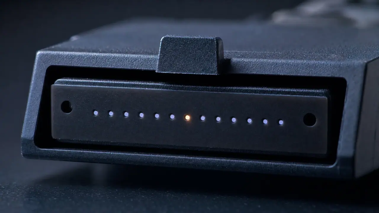
The strand count is visible at the panel: every 400G port on the card above costs sixteen, eight, or two of these fibers.
The five decisions, in the order they bind
Designers get into trouble by treating these as independent choices. They are a chain: each one eliminates options for the next, and skipping ahead is how you end up specifying a connector that no available optic can drive.
- Reach. Physical distance picks the PMD family — and nothing else can override it.
- Media. Multimode or single-mode follows from the PMD, not from preference or from what is on the shelf.
- Lane count. The PMD's lane structure dictates fibers per port: 2, 8, 16, or 32.
- Connector and polish. Fiber count picks the connector; the module, not the media, picks the polish — at 400G, multimode uses APC too; the panel design picks pinned or unpinned.
- Polarity and loss margin. These are properties of the assembled channel, and they are what a clean insertion-loss test will not catch.
Work down that list and the design closes. Work up it — start with a connector you like, or a cable that is already in stock — and you will spend the commissioning window discovering decisions you did not know you had made.
Reach picks the PMD before you pick anything else
Four standards generations produced the 400G optics you can buy today: IEEE 802.3bs for the first 400G PMDs, 802.3cm for the multimode parts, 802.3cu for 100G-per-lane single-mode, and 802.3db for short reach at 100G per lane. You do not need to memorise the clause numbers; you need the table they produce.
PMD | Media | Fibers per port | Connector | Reach | Standards family |
|---|---|---|---|---|---|
400GBASE-SR16 | OM4 multimode | 32 | 1 × 32-fiber MPO-16 (two rows) | 100 m | 802.3bs |
400GBASE-SR8 | OM4 / OM5 multimode | 16 | MPO-16 APC | 100 m | 802.3cm |
400GBASE-SR4.2 | OM4 / OM5 multimode | 8 | MPO-12 UPC | 100 m (OM4) / 150 m (OM5) | 802.3cm |
400GBASE-SR4 | OM4 multimode | 8 | MPO-12 (check datasheet) | 100 m | 802.3db |
400GBASE-VR4 | OM4 / OM5 multimode | 8 | MPO-12 APC | 50 m | 802.3db |
400GBASE-DR4 | OS2 single-mode | 8 | MPO-12 APC | 500 m | 802.3bs |
400GBASE-FR4 | OS2 single-mode | 2 | Duplex LC UPC | 2 km | 802.3cu |
400GBASE-LR4-6 | OS2 single-mode | 2 | Duplex LC UPC | 6 km | 802.3cu |
400GBASE-LR8 | OS2 single-mode | 2 | Duplex LC UPC | 10 km | 802.3bs |
Three things the table makes obvious and vendor pages tend to bury. First, the polish column, which reseller tables usually drop: at 400G it is set by the module, not by the glass, so the same OM4 plant wants APC on an SR8 port and UPC on an SR4.2 one. Second, the module form factor — QSFP-DD or OSFP — changes the thermal and power budget, not the fiber count: OSFP's larger shell buys thermal headroom for the hotter parts while QSFP-DD keeps backward compatibility with existing QSFP28 line-card slots, and the same PMD appears in both cages with the same connector on the front. Third, for the shortest runs inside a rack, a fixed active optical cable or DAC removes the connector decision altogether, because it ships as one assembly with the modules built in.
Two entries in that table — really two families — change projects, and they are the two vendors rarely put next to each other.
SR16 is the ancestor. Thirty-two fibers and sixteen 25G lanes, from the first 400G generation. It exists in the catalog and you should not design new plant around it.
The 8-fiber rows are the ones that save a building. SR4, SR4.2 and VR4 all carry 400G over the same eight fibers and the same MPO-12 connector that 100G-SR4 uses, by running 100G per lane PAM4 instead of 50G — SR4.2 does it on two wavelengths over four pairs. If your building is base-8 or base-12 multimode, they cost you nothing in fiber, and none of them is new: SR4.2 arrived with 802.3cm in 2020, SR4 and VR4 with 802.3db in 2022. Together they are the reason "400G means MPO-16" is no longer true as a blanket statement. SR4 holds the full 100 m; VR4 is the 50 m member, which covers the GPU-to-switch leaf runs that made 400G a rack-scale problem in the first place.
Module-to-connector pairings are worth checking against a first-party document rather than a reseller table — Cisco's 400G optics and cable ordering guide is the clearest public one, and it also confirms a detail that matters later: forward error correction is performed on the host platform, not inside the module.
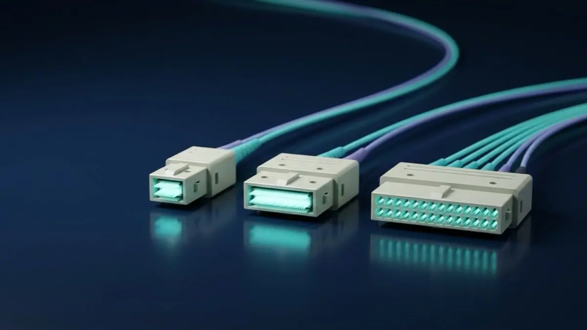
The connector count follows the PMD, not the other way round: 16-fiber single-row for SR8, 12-fiber for every 8-fiber 400G PMD.
Multimode or single-mode: the 100 m line
The media decision collapses to one distance. Below roughly 100 m inside a hall, multimode with VCSEL-based optics is the cheapest way to move 400G. Above it — or anywhere the run leaves the building — single-mode wins, and at 400G it wins earlier than people expect, because DR4 reaches 500 m over eight single-mode fibers.
That is a big deal for campus and multi-hall layouts. A 300 m run between two halls is not an exotic long-haul case; it is a DR4 link on MPO-12 single-mode, at a module cost close to multimode and with none of the bandwidth-distance anxiety. Our OS2 vs OM4 vs OM5 comparison covers the fiber grades themselves; for the purposes of a 400G channel, three facts decide it:
- OM4 is the working default at 850 nm and carries every multimode 400G PMD to 100 m.
- OM5 is OM4 plus a bandwidth specification at 953 nm — the wideband case for multi-wavelength links. It does not extend reach for single-wavelength 850 nm optics; there, its 850 nm performance is OM4's. The one 400G number it does move is SR4.2: 150 m on OM5 against 100 m on OM4. Corning's own 800G multimode paper states the numbers plainly: 4700 MHz·km at 850 nm, 2470 MHz·km at 953 nm.
- Past 2 km, single-mode stops being a cost argument and becomes the only option — and by then you are on duplex LC, which is a different cable plant entirely.
The practical consequence: if you are cabling a hall, multimode. If you are cabling between halls, price DR4 on single-mode before you assume multimode plus a repeater.
Fiber count is the constraint that outlives the optic
Optics get replaced every generation. Trunks get replaced when the building is refurbished. That asymmetry is why the strand count deserves more thought than the module.
Channel system | Connector | Fibers per 400G port | Ports per 32-fiber bundle |
|---|---|---|---|
Base-8 / base-12 | MPO-12 | 8 (SR4, SR4.2, VR4, DR4) | 4 |
Base-16 | MPO-16 | 16 (SR8) | 2 |
Base-32 | 1 × MPO-16 (32F) | 32 (SR16) | 1 |
Read the last column as a budget. The same glass that carries 2 ports on SR8 carries 4 on SR4. That is not a small efficiency difference; it is the difference between a trunk that lasts through the 800G transition and one that has to be pulled.
Base-16 is the right greenfield answer for 400G and beyond because 16 fibers fill an MPO-16 exactly — eight transmit, eight receive, nothing stranded — and because 800G SR8 rides the same footprint as eight 100G lanes. CommScope's 400G/800G migration fact file makes the case directly: 16-fiber architectures are what allow a 400G circuit to be subdivided into 50G and 100G links without re-cabling.
Base-8 is the right brownfield answer. If a hall already has MPO-12 trunks, 400G over SR4 keeps them, and the stranded four fibers in each connector stop being waste and become your migration reserve. The trade-off is real: 8-fiber PMDs carry a 400G port on four 100G lanes across eight fibers, so the module catalogue is narrower — SR4, SR4.2 and VR4 only — with reach of 50–150 m depending on the PMD and the fiber grade, against 100 m for SR8 on OM4.
What you should not do is mix the two inside one channel. MPO-16 will not mate with MPO-12 — different ferrule width, different key offset — so a base-16 trunk cannot land on a base-8 cassette, and nothing mates them directly. If the design has to cross that line, it crosses it at a patch panel with two different connector families on opposite sides, and that panel is a deliberate, documented decision, not an accident discovered during installation. Our MPO vs LC high-density cabling covers the duplex alternative — MDC and SN connectors — which is worth pricing when port density, not strand count, is the binding constraint.

Where the channel ends: duplex LC pairs at the leaf switch. Each aqua or orange pair carries one lane's transmit and receive — the point at which a trunk's fibers become ports.
Polarity and pinning: the failures a clean loss test hides
Here is the failure mode that eats commissioning windows: a channel that passes insertion loss with margin and still delivers nothing, or delivers half.
Polarity is the mapping of transmit to receive across the whole channel. Three methods — A (straight), B (crossover), C (pair-reversed) — are all legitimate, and all three exist at 16 fibers as well as 8. The rule is not "use Method B". The rule is one method, end to end, through every trunk, cassette, harness and patch cord in the channel. A Method B trunk landing on a Method A harness produces transmit-to-transmit: light leaves one port and arrives at the other port's transmitter. Loss tests look fine, because loss is what they measure. The detailed mapping, including how 8-fiber and 16-fiber methods differ, is in our MPO polarity Type A/B/C guide.
Pinning is the physical half of the same problem. Every MPO mating needs guide pins on one side and holes on the other. Order a pinned-to-pinned pair and they will not seat; order unpinned-to-unpinned and the ferrules have nothing to align them, so the loss numbers drift with every re-mate. Specify male/female per position on the BOM and verify against the port you are plugging into — not against last year's spreadsheet.
At 16 fibers there is a third trap that catches experienced installers: the harness. A 400G SR8 port fans out to 8 × 50G or 2 × 200G, and the fan-out assembly carries its own polarity and its own pinning. A harness built for a base-8 system will not mate with a base-16 port at all — different ferrule — and re-pinned to fit it would connect and then miswire. When you order 16-fiber assemblies — which are built to order rather than stocked, including our MTP-to-MTP trunk cables — put the polarity method and the pinning on the purchase order, not in an email.
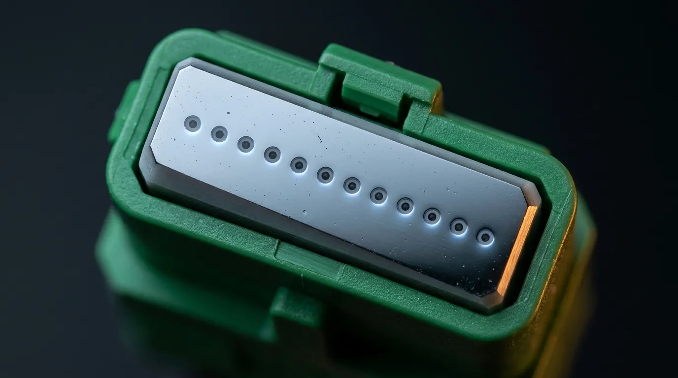
Polish is not cosmetic, and it is not a media rule. The 8-degree APC ferrule returns light away from the laser; at 400G it appears on multimode MPO ports (SR8, VR4) as well as single-mode ones.
Which polish goes where is not a media rule, and this is the most expensive assumption in 400G cabling: the polish is set per PMD, by the module. Multimode runs APC as readily as single-mode does at these rates. Cisco's 400G QSFP-DD data sheet says its SR8 module "requires MPO-16 APC for MMF", lists VR4 and DR4 among the parts that need APC patch cords, and documents SR4.2 as MPO-12 UPC — the one multimode 400G part in that catalogue that stays flat. SR4 sits outside that list, so take its polish off the datasheet rather than inferring it from the fiber. Order a UPC 16-fiber trunk for an SR8 port and you have a channel that either will not mate or fails return loss at the first acceptance test. What is absolute is the half everyone remembers: never mate APC to UPC. A DR4 link built with UPC MPO on OS2 will often run — with a return loss that quietly eats the margin the FEC is covering for. Our MPO/APC single-mode assemblies are specified at ≥60 dB return loss for exactly this reason.
The loss budget nobody publishes for 400G
Module datasheets give you reach. They do not give you the channel arithmetic, and 400G is where that gap bites, because the connector count per port doubles while the reach stays at 100 m.
The arithmetic has a published ceiling. Every 400G PMD is specified with a maximum channel insertion loss covering the whole path from module to module: 1.9 dB for 400GBASE-SR8 over OM4 at 100 m (IEEE 802.3cm, Clause 138) and 3.0 dB for 400GBASE-DR4 over 500 m (802.3bs, Clause 124). Both are tabulated in TIA's application overviews for 400GBASE-SR8 and 400GBASE-DR4, and that ceiling — not the module's reach — is what a field test is graded against.
Use the classic method — source power minus receiver sensitivity minus margin — with planning values that hold up at 400G:
Element | Measured range | Planning value |
|---|---|---|
Single-mode fiber, 1310 nm | 0.35–0.40 dB/km | 0.40 dB/km |
Multimode fiber, 850 nm | ~3.5 dB/km | 3.5 dB/km |
Mated MPO pair, low-loss grade | 0.1–0.35 dB | 0.35 dB |
Mated duplex LC pair, good polish | 0.1–0.3 dB | 0.30 dB |
Fusion splice, single-mode | ≤0.05 dB | 0.15 dB |
Splice, multimode (usually mechanical) | 0.1–0.5 dB | 0.30 dB |
FOA's loss budget reference is the method source, and two of its numbers are worth reading precisely because they get copied wrongly. The 0.75 dB it lists per mated pair is labelled TIA-568 maximum acceptable — a pass/fail ceiling for a connector population, not what a low-loss MPO assembly measures, and FOA itself calls it "generally much too high" outside array connectors. Its multimode splice figure is 0.1–0.5 dB, "0.3 being a good average for an experienced installer" — three times the number people carry over from single-mode fusion tables. Budget the multimode channel with 0.3 and the arithmetic tells you the truth.
Now build two channels.
A 100 m multimode channel at 400GBASE-SR8 with a realistic topology — patch cord at the switch, trunk, cassette, patch cord at the server — has four mated pairs. At 0.35 dB that is 1.4 dB of connector loss, plus 0.35 dB of fiber (100 m at 3.5 dB/km): 1.75 dB against the 1.9 dB limit. That leaves 0.15 dB for everything else — and there is no everything else. Add one multimode splice at the 0.3 dB average and the channel sits at 2.05 dB, over the limit before a single repair or re-mate.
A 300 m single-mode channel at 400GBASE-DR4 over the same four-pair topology costs 1.4 dB of connectors, 0.12 dB of fiber and 0.3 dB for two fusion splices: 1.82 dB against DR4's 3.0 dB limit — 1.18 dB of headroom.

The topology behind that arithmetic: an MPO trunk landing in a panel, duplex LC legs out the front. Every point where two connectors meet along the chain is a mated pair — four of them in the channel above.
The conclusion is counter-intuitive and worth carrying into every design review: at 400G, distance is cheap and connectors are expensive. Adding 200 m of single-mode costs 0.08 dB, and the 100 m of multimode glass under an SR8 port costs 0.35 dB — exactly what one extra mated pair costs. Removing a mated pair recovers 0.35 dB, which is 875 m of single-mode fiber, and more than twice the entire margin the multimode channel had left. If a channel is marginal, the fix is almost never "shorter cable". It is "one fewer cassette" or "a harness instead of a trunk plus two patch cords".
Two practical rules follow. First, take the PMD's channel insertion-loss limit — 1.9 dB for SR8 on OM4, 3.0 dB for DR4 — and subtract the planning column. If the remainder is under about 0.5 dB you already have your answer: delete a mated pair before you order, because that pair costs as much as the whole span of glass. Second, remember that 400G Ethernet relies on forward error correction performed by the host, so a link that comes up is not proof of a healthy channel — FEC is covering for margin you no longer have. For how much loss is normal on a fiber link in general, our dB loss reference puts these numbers in a wider context.
What a 400G migration actually costs in fiber
The migration from 100G is usually described as a speed change. It is a strand-count change, and the arithmetic is unforgiving.
Take a leaf with 32 downlinks moving from 100G-SR4 to 400G. On SR8 you need 512 fibers — twice what the 100G design used, in a connector family the plant does not have. On any of the 8-fiber PMDs — SR4, SR4.2, VR4 or DR4 — you need 256, which is exactly the fiber count the 100G design already used, and on multimode that means an optic swap with no cabling work at all. On FR4 you need 64, at the cost of a duplex plant that cannot break out.
That last word matters. Breakout is what makes 400G affordable during a phased migration, and it is not available on every PMD. A DR4 port breaks out to 4 × 100G, which lets you keep 100G leaf ports while the spine moves to 400G. An SR8 port breaks out to 8 × 50G or 2 × 200G, per Cisco's ordering guide. FR4 and LR4 do not break out at all — their four wavelengths are multiplexed inside the module and emerge as one duplex pair. If your migration plan assumes breakouts, the PMD choice has already made it for you.
There is a cheaper path than any of this, and it is worth naming: overlay rather than convert. Run new base-16 trunks for the 400G spine, leave the 100G leaf plant alone until the leaf refresh, and accept a period where two cabling systems coexist in the same racks. It costs panel space and documentation discipline, and it avoids the one outcome nobody budgets for — a hall-wide re-trunk driven by a speed upgrade that was supposed to be an optics swap.

Breakout is where a 400G port becomes four 100G ports again — and where the harness polarity has to match the trunk's.
Commissioning: what to test and what number passes
Three tests, in this order, and each one catches a different failure.
- End-face inspection on every MPO connector before mating. A single contaminated fiber in a 16-fiber ferrule costs you a channel; cleaning is cheaper than a re-visit. Inspect, clean, inspect again.
- Per-fiber loss, not per-connector loss. A 16-fiber channel has 16 paths, and a cassette with one bad position passes a single-ended test while failing one lane. Test with reference cords matched to the channel — the one-cord method includes both end connections, the three-cord method excludes them, and mixing the two produces numbers you cannot compare across a project.
- Polarity verification by measurement. Do not accept a label. Confirm each lane transmits to the far-end receiver it is supposed to reach, especially on any channel assembled from parts sourced at different times.
One safety rule belongs in the same procedure: never look into a fiber end face, a connector ferrule or an empty adapter port, and treat a visual fault locator as the live laser it is. Measure with a power meter first; inspect end faces through a scope, never with the eye.
Record the results against the channel, not against the cable. When a link degrades in eighteen months, the only useful baseline is the loss number the channel had when it was accepted.
One definitional trap before you write the acceptance criteria: a permanent link stops at the patch panel, while a channel includes the equipment cords at both ends — the TIA-568 split. The same run of glass can pass one and fail the other, so agree on which one the contract names before the first measurement, not after the first failure.
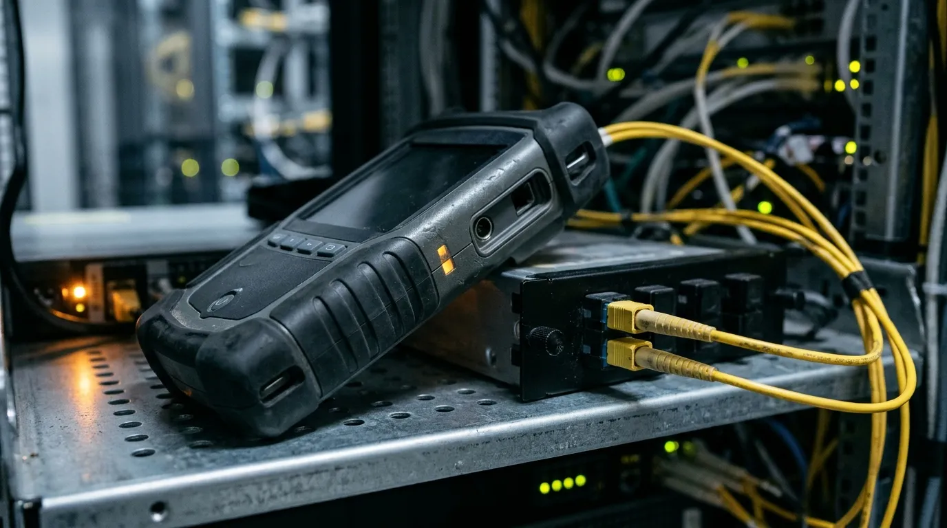
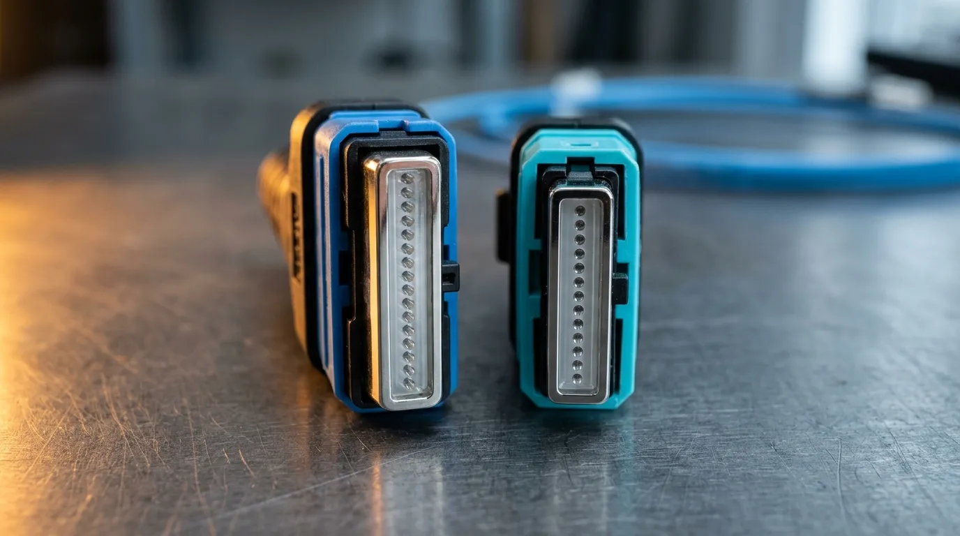
Per-fiber loss at the panel, with reference cords matched to the method — the only number that means anything across a project.
The specification sheet to hand your supplier
Everything above compresses into ten lines. Put them on the purchase order.
- PMD and reach — the exact 400GBASE part, and the longest channel it must serve
- Media — OM4, OM5, or OS2, with the grade named, not "multimode"
- Fibers per assembly — 8, 16, 24, or 32, matching the PMD (not the old plant)
- Connector type per end — MPO-12, MPO-16, LC duplex, and the gender at each position
- Polish — per module, not per media: MPO-16 APC for SR8, MPO-12 APC for VR4, MPO-12 UPC for SR4.2, MPO-12 APC for DR4
- Polarity method — A, B, or C, stated once and applied end to end
- Pinning — male or female per port
- Length — measured along the cable path, including slack and bend radius
- Test data — per-fiber insertion loss and return loss for every assembly, delivered with the goods
- Jacket and rating — plenum or riser per the pathway, per the local code
That list is also the most useful thing you can send a manufacturer, because it forces the two questions that get skipped: which method is already installed in this hall, and which port does this end plug into. Those two answers prevent more 400G commissioning failures than any datasheet.
When you would rather have the assemblies built to that sheet than specify them from scratch, TTI Fiber builds them to order — MPO harness fan-outs from 8 to 72 fibers and MTP trunks from 12 to 72, polarity A/B/C and male/female pins configured per end, factory-terminated and 100% tested, with the per-channel insertion-loss and return-loss data shipped alongside the goods.
If the plant decision is still open — for instance, if you are weighing base-16 greenfield against keeping base-8 and moving to SR4 — start with the data center cabling hub for the connector, polarity, and fiber-grade references, then bring the strand arithmetic to the design review. The optic will be obsolete before the trunk is.