FTTR Topology Design: Star vs Bus
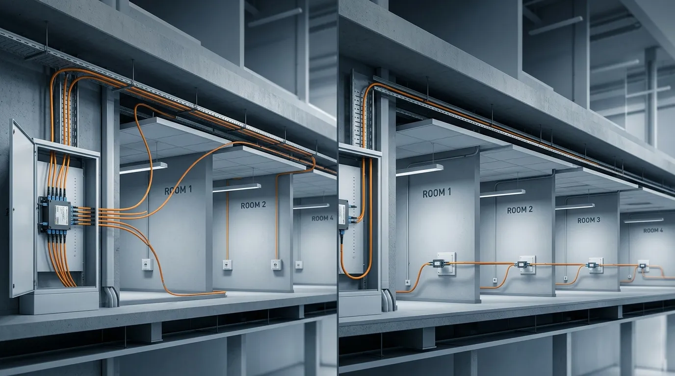
Every FTTR design starts with the same fork in the road: do you run one fiber from a central splitter to every room, or do you run a single fiber and chain the rooms along it? The choice — star versus bus topology — decides your optical loss budget before you buy a single component, and it is nearly impossible to change after the fiber is in the wall. This guide compares both topologies on the criteria that actually matter in the field — loss, fiber count, scalability, fault isolation, and installation effort — then walks you through a selection process and a loss-budget calculation you can apply to your own project.
If you are new to the architecture underneath, our FTTR overview covers the components (master ONT, PLC splitter, room ONTs) and the F5G context, and the FTTR resource hub collects the full series; the rest of this guide assumes you know what FTTR is and need to decide how to lay it out.
Star Topology: One Splitter, Fiber to Every Room
A star (or "home-run") topology gives every room its own dedicated fiber path back to a central point. In an FTTR network the central point is the master ONT (also called the main gateway), and the fan-out happens at a passive optical splitter: the master's PON port feeds one fiber into a PLC splitter, and each output leg runs as a dedicated drop to one room's slave ONT. This is the point-to-multipoint (P2MP) structure that defines FTTR as a PON system rather than an Ethernet system — the ITU-T supplement on FTTR for small-business applications highlights the P2MP topology as a core reason FTTR can shrink the head-end compared with switching-based in-building networks (ITU-T G.Suppl.78, clause 6).
Split ratios in FTTR star designs are typically 1:4 or 1:8, with 1:16 used in larger multi-dwelling units. Each split adds a fixed loss (a 1:4 splitter adds roughly 7 dB, 1:8 about 10.5 dB, 1:16 about 13.8 dB — exact figures below), and that loss is paid exactly once, regardless of how many rooms you add. That is the defining property of a star: loss does not accumulate with room count.
The star's advantages show up at every stage of the project:
- Predictable loss budget. Every room sees the same splitter loss plus its own short drop-cable run, so you size the budget once and it holds for all rooms.
- Fault isolation. A problem in one room's drop affects only that room. The splitter is passive, so the other legs keep working untouched.
- Independent upgrade path. Rooms can be upgraded one at a time (higher-rate ONT, extra service) without touching the rest of the network — the fiber in the wall is future-proof, and upgrading later is mostly a device swap. The FTTR systems literature describes exactly this evolution path (arXiv:2504.20433).
- Simpler commissioning. All drops terminate at a central patch point, so testing and troubleshooting happen in one place.
The cost of the star is fiber and labor: one drop cable per room, each run from the splitter location to the room. In a new build or a full renovation, that is rarely a problem — conduit and wall chases are open anyway. In a retrofit where you are trying to reuse one existing cable route, it can be the deal-breaker that pushes you toward a bus.
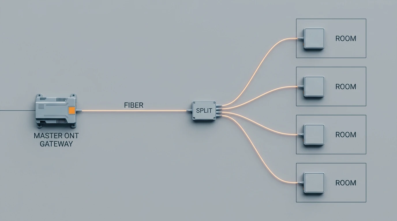
Star topology: one splitter, one dedicated fiber drop per room, and a flat loss budget no matter how many rooms you add.
Bus Topology: One Fiber, Rooms in a Chain
A bus (or daisy-chain) topology runs a single fiber through the building and taps each room off it in sequence: master ONT → room 1 → room 2 → room 3, with each room's ONT taking its signal from the passing fiber. The technical term for this is cascaded or chain topology, and it is the architecture you end up with when an Ethernet-switch-based in-building network is replaced with fiber running through the same conduits.
The appeal is obvious: one cable route serves every room. In a retrofit where a single conduit already snakes through a corridor or a row of rooms, a bus can be installed with a fraction of the fiber and a fraction of the pulling work of a star. The same ITU-T supplement that defines FTTR's P2MP rationale also describes cascaded splitter arrangements in FTTR ODNs — including unbalanced splitters used to equalize optical path loss across the chain (clause 7.8) — so a bus is a recognized, standards-adjacent way to build an FTTR network, not a hack.
The bus pays for that economy in three places:
- Loss accumulates with every hop. Each tap adds insertion loss, and the last room in the chain sees the sum of all of them. A chain of eight rooms can easily eat 15–20 dB before the receiver, where a star would have cost ~10.5 dB total. The loss budget — not the fiber count — is what caps how long a bus can be.
- Every hop is a potential failure point. A bad connector or a broken tap in room 3 takes down rooms 4 through 8. In a star, no room depends on any other room's installation quality.
- Expansion means breaking the chain. Adding a room at the end extends the chain and increases loss for the newest (and worst) link; adding a room in the middle requires splicing into a live fiber.
The ITU analysis of in-building networks is blunt about why switching-based chains are limited for this use: the scale of enterprise/small-business networking and the complexity of managing many active links are exactly the problems FTTR's P2MP architecture was designed to remove (clause 5 of the same supplement). A bus is the fiber version of that same chain — it works, and it is the right call in a narrow set of retrofit conditions, but it inherits the chain's structural weaknesses.
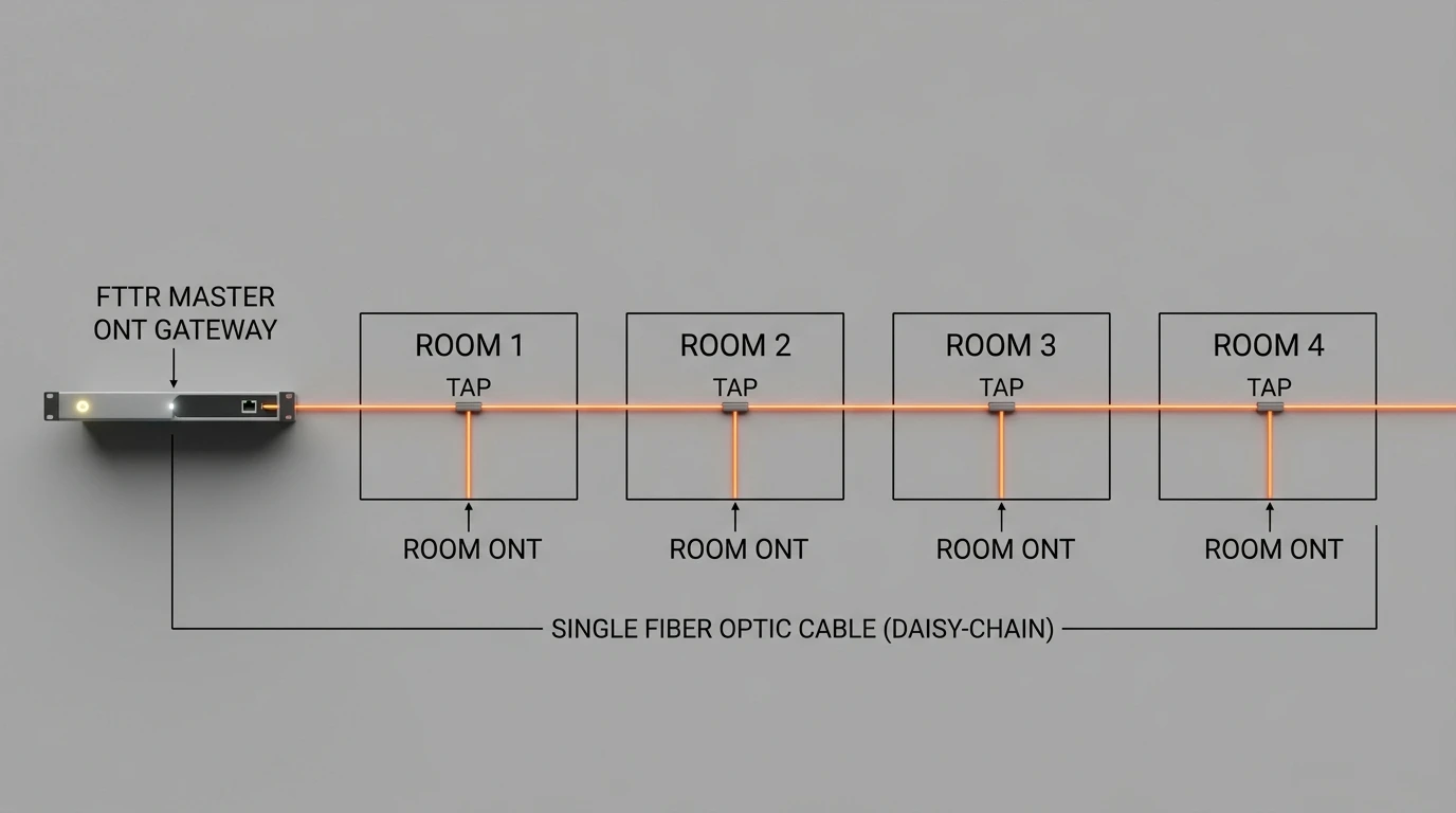
Bus topology: one fiber, rooms tapped off in sequence — less cable, but loss and failure risk grow with every hop.
Star vs Bus FTTR: Head-to-Head Comparison
Criterion | Star (home-run via splitter) | Bus (daisy-chain via taps) |
|---|---|---|
Fiber required | One drop per room (more fiber) | One route for all rooms (less fiber) |
Splitter loss | Paid once (7–13.8 dB for 1:4–1:16) | Accumulates per hop (chain-length dependent) |
Loss budget scaling | Flat — room count doesn't change it | Grows with room count — hard ceiling |
Fault isolation | Per-room — one bad drop doesn't cascade | Cascade — a bad tap kills downstream rooms |
Adding a room later | Terminate another splitter leg | Extend the chain; loss grows again |
Installation effort | More pulls, more fiber | One pull, less fiber |
Best building type | New builds, renovations, MDUs, offices | Retrofit with one existing conduit route |
The pattern is consistent: star wins on every performance criterion; bus wins on one — installation economy in a retrofit. That is why the industry default is star, and why bus is a conditional exception rather than a competing default. The conditions that justify the exception are specific enough to spell out, which is what the next section does.
How to Choose: Decision Rules by Building Type
Work through these in order; the first rule that matches your project tells you your topology.
Your project | Recommended topology | Split ratio | Why |
|---|---|---|---|
Single-family house, new build or full renovation | Star | 1:4 or 1:8 | Walls are open; home-run drops cost little; per-room performance and isolation matter most |
Single-family house, retrofit with an existing conduit run | Star if you can pull 2–4 drops; bus only if truly one route | 1:4 | Check the conduit: if more than one drop can be pulled, star still wins on loss and isolation |
Apartment / multi-dwelling unit | Star from a central distribution point (floor cabinet or riser) | 1:8 or 1:16 | Central splitter per floor or per riser keeps every unit's loss identical and manageable |
Small office (5–20 rooms) | Star | 1:8 | Uniform loss, central patching at the comms cabinet, per-office fault isolation |
Hotel / dorm / long-corridor retrofit, single existing cable route | Bus — and verify the budget first | Chain of ≤4–6 rooms | Only scenario where bus is defensible; cap the chain length so the last room still clears the receiver sensitivity |
Any project where you expect to add rooms or upgrade speeds later | Star | 1:4–1:8 | The fiber in the wall is the part you can't redo; star keeps upgrade headroom open |
Two hard rules from the field:
- Never choose bus because "it's fewer fibers." Bus saves fiber but spends loss budget and fault isolation. It is justified only by physical constraints — a single unreplicable conduit route.
- When in doubt, count the rooms. If the bus chain would exceed ~6 rooms or the computed loss at the last room would exceed your receiver margin, bus is off the table regardless of the conduit situation.
Calculating the Optical Power Budget
The loss budget is the arithmetic that decides whether your topology survives. The formula is the same for every link:
Total loss = splitter loss + connector/splice losses + fiber attenuation + margin
Splitter loss dominates. Use the maximum (worst-case) figures from the splitter's spec sheet, not the typical ones — you want the budget to hold for the worst unit in the batch:
Split ratio | Typical loss | Max loss |
|---|---|---|
1:4 | ~7.0 dB | 7.3 dB |
1:8 | ~10.2 dB | 10.5 dB |
1:16 | ~13.5 dB | 13.8 dB |
(These are the published worst-case specs for TTI Fiber's 1x4, 1x8, and 1x16 PLC splitters, which are representative of current PLC splitter performance across manufacturers.)
Connector and splice losses: budget 0.3–0.5 dB per mated connector pair and ~0.1–0.2 dB per splice. A typical FTTR room link has 4–6 connector points (splitter output, patch panel, wall box, ONT), so count 1.5–3 dB for a star drop.
Fiber attenuation: indoor single-mode fiber adds ~0.3–0.4 dB/km — for in-building runs of tens of meters this rounds to near zero. It matters only for campus-scale runs, and you should not add more than a few tenths of a dB for it in an FTTR design.
Receiver margin: keep at least 3 dB of headroom above the ONT's rated receiver sensitivity. This absorbs connector aging, dust, and the occasional bad termination — the things that turn a "theoretically fine" link into a 1 a.m. service call.
Star example (8 rooms, 1:8 splitter, worst case):
Splitter (1:8 max) 10.5 dBConnectors (5 pairs) 2.0 dBFiber (50 m @ 0.35 dB/km) 0.02 dBMargin 3.0 dBTotal ~15.5 dB
A typical GPON or XGS-PON ONT is specified for a ~27–28 dB total link budget (the ITU-T G.984.2 physical-layer classes define the allowed loss between OLT and ONT), so this link sits comfortably inside — and the same number applies to all eight rooms. That flatness is the star's whole point.
Bus example (8 rooms chained, taps at ~1.2 dB each + 2 connectors per hop):
Tap losses (8 × ~1.2 dB) 9.6 dBConnector losses (16 pairs) 6.4 dBFiber ~0.1 dBMargin 3.0 dBTotal ~19.1 dB (last room in chain)
The last room burns ~19 dB before the receiver — 3.6 dB worse than the star's worst room, with six times the connector count to go wrong, and the first room's failure takes out the rest of the chain. Stretch the chain to 12 rooms and the last link approaches the ONT's ceiling with zero margin left. This is the calculation that caps bus chains at ~4–6 rooms in practice. For a deeper treatment of how splitter loss behaves in PON networks, see our guide to passive splitter insertion loss.
Design Steps: From Room Count to a Cabling Plan
Before you start: you need a floor plan with room locations, a count of rooms that need wired connectivity (not just Wi-Fi), the planned line rate (1 Gbps, 2.5 Gbps, or 10 Gbps PON), and a survey of existing conduits if this is a retrofit.
Step 1 — Count rooms and bandwidth. List every room that needs a wired drop: home offices, bedrooms with streaming/VR, living areas, plus any room that will host a high-density device cluster (cameras, IoT hubs). Bandwidth per room rarely matters for topology — PON gives every room the full line rate — but it matters for split ratio headroom and for whether you need XGS-PON over GPON.
Step 2 — Pick the topology (30 seconds with the table above). Match your building type to the decision table. New build or renovation → star. Retrofit with one existing route → check the bus's loss at the last room before committing.
Step 3 — Choose the split ratio from the loss budget. With your topology fixed, run the power budget from the previous section. If 1:16 puts you under ~6 dB of margin, step down to 1:8; if 1:8 is overkill for 6 rooms, step down to 1:4. The rule: smallest ratio that covers your room count with ≥3 dB margin.
Step 4 — Plan fiber and routing. For new builds, standard indoor single-mode drop cable or invisible fiber optic cable (transparent, for surface-mount on walls/ceilings) both work; keep bend radius above the cable's rated minimum (typically ≥30 mm for drop cable, ≥15 mm for bend-insensitive types) at every corner. For retrofits, verify the conduit diameter against the cable jacket and count the existing cables in it. Most FTTR systems run a single fiber to each room — upstream and downstream share one strand via WDM — while some deployments use dual-fiber drops; check the room ONT's port type before you order cable, because the two are not interchangeable.
Step 5 — Fix the master location and termination points. The master ONT (and its splitter) belongs at the point where the incoming service fiber enters — typically a utility closet, garage, or living-room corner. Put the splitter where the average drop length is shortest, terminate every drop at a wall box in each room, and label both ends. The master's job — centralized scheduling and control of the room ONTs — works the same regardless of topology, as the FTTR system architecture literature describes.
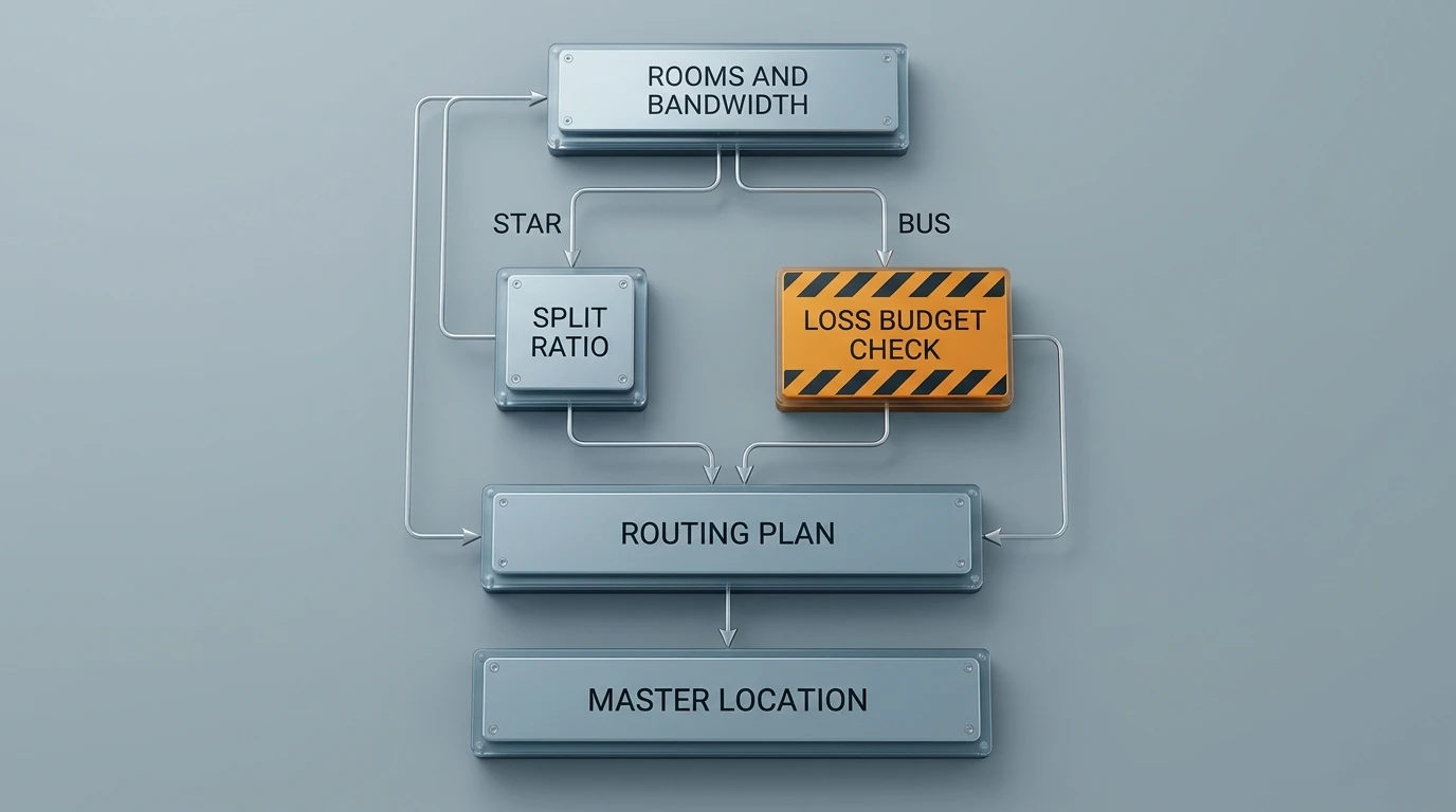
The five-step design flow: count rooms, pick topology, size the split ratio from the loss budget, plan routing, then fix the master location.
When you're done, you should have: a topology decision, a computed loss budget with ≥3 dB margin at every room, a split ratio, a routing plan with bend-radius check, and a labeled termination plan. If you can't state all five, go back — the missing one is where the project will fail.
Components You'll Specify for an FTTR Build
Whatever topology you chose, the component list is the same — only quantities and split ratio change:
- Master ONT / main gateway — terminates the service fiber from the ISP, hosts the PON port that feeds the splitter, and manages the room ONTs (channel assignment, roaming, power saving). Check: number of PON ports, whether it matches your split ratio, management interface.
- PLC optical splitter — the passive heart of a star. Check: insertion loss (use the max column in your budget), uniformity across ports (≤1.5 dB is typical for 1:16), and package form (bare fiber for splicing into a distribution box, ABS box, or LGX cassette for rack mounting). Our PLC splitter product line covers 1x4 through 1x64.
- Indoor drop cable or invisible fiber — the physical layer between splitter and room. Check: bend radius rating, jacket material (surface-mount invisible fiber vs duct-rated drop cable), connectorization.
- Room ONT (slave unit) — terminates the drop in each room and provides Wi-Fi (typically Wi-Fi 6) plus a LAN port. Check: upstream PON type (GPON/XGS-PON), Wi-Fi standard, mounting.
- Wall boxes / terminal boxes — protect the splice between drop and pigtail at each end. Check: fiber capacity, whether it accommodates a splice tray.
- Connectors and adapters — almost always SC/APC in FTTR (APC reduces reflection in PON). Check: ferrule polish type — mixing UPC and APC in one link is a classic silent failure.
For a full rundown of splitter options and when each package makes sense, our guide to optical fiber splitter types walks through bare-fiber, ABS, and cassette forms.
Final Checklist Before You Start Pulling Fiber
Designing an FTTR network is a short list of decisions — topology, split ratio, routing, termination — and every one of them is checkable on paper before installation starts. The star-versus-bus choice is the one that locks in the loss budget, so it is the one worth getting right first. If you're specifying components for an FTTR project and want the numbers checked against real hardware, TTI Fiber's engineering team works with integrators on splitter selection, drop cable, and ONT compatibility — send us your room count and floor plan and we'll run the budget with you.