What Is FTTR? Fiber to the Room Explained
What Is FTTR?
FTTR (Fiber to the Room) is an in-building optical network architecture that extends fiber optic cable beyond the building entry point directly into individual rooms, where dedicated optical network terminals (ONTs) provide full-rate gigabit connectivity and Wi-Fi 6 coverage at each endpoint. It is the access-layer realization of the F5G (Fifth Generation Fixed Network) vision defined by ETSI, and it is standardized under ITU-T G.fin, which specifies the architecture, physical layer, and data link layer for fiber-to-the-room deployments.
If you have worked with fiber access networks, you already know the pattern: FTTB brought fiber to the building in the 10-megabit era, FTTH brought it to the home for 100-megabit services, and now FTTR completes the journey — bringing fiber all the way to the room in the gigabit era. (For a structured comparison of these architectures, see our guide to FTTx access network architectures.) The difference is not academic. It changes which components you specify, how you design the indoor distribution network, and what performance guarantees you can make to end users.
Why FTTR Now? The Problem FTTH Left Unsolved
FTTH solves the last-mile problem. It delivers a fiber connection to an ONT mounted at the building entry point — typically in a utility closet, garage, or living room corner. From there, the in-premises network takes over: copper Ethernet cables to a router, Wi-Fi through walls, maybe a powerline adapter for the far bedroom.
The bottleneck is the in-premises distribution layer. A 5 GHz Wi-Fi signal loses 30–50% of its throughput passing through a single interior wall. Two walls, and a gigabit connection at the ONT becomes 150 Mbps in the back office. Mesh Wi-Fi systems help — but each wireless hop still bleeds bandwidth, and the backhaul channel competes with client traffic for airtime.
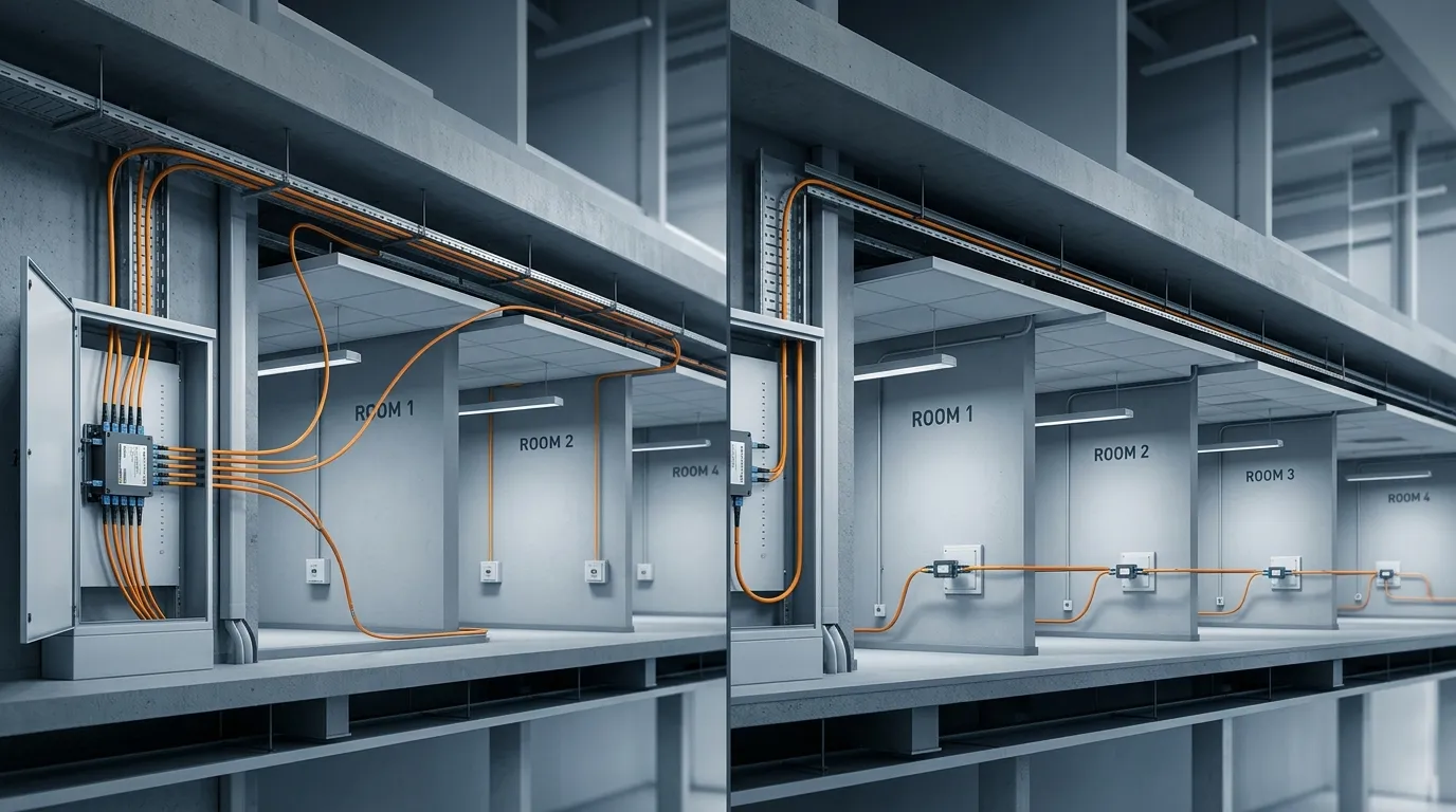
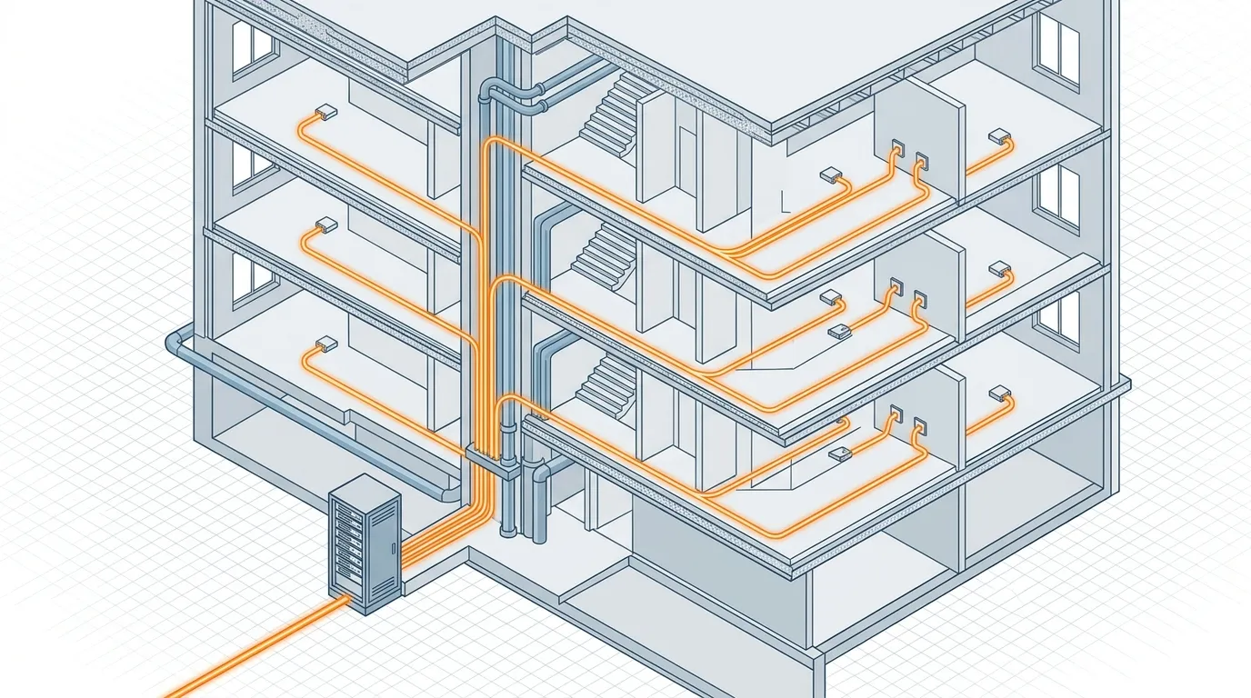
FTTR eliminates this problem at the physical layer. Instead of relying on copper or wireless backhaul inside the building, it runs optical fiber from a central distribution point to an ONT in every room. Each room gets the full line rate, not whatever survives the wall attenuation. For services like 8K streaming, cloud VR, multi-user video conferencing, and dense smart-home device counts — all pushing against the limits of wireless-only in-building networks — this is not a luxury. It is becoming a deployment requirement.
How FTTR Works: Architecture and Components
An FTTR network follows a PON (Passive Optical Network) topology inside the building, mirroring the architecture used in the outside plant but scaled for indoor distances:
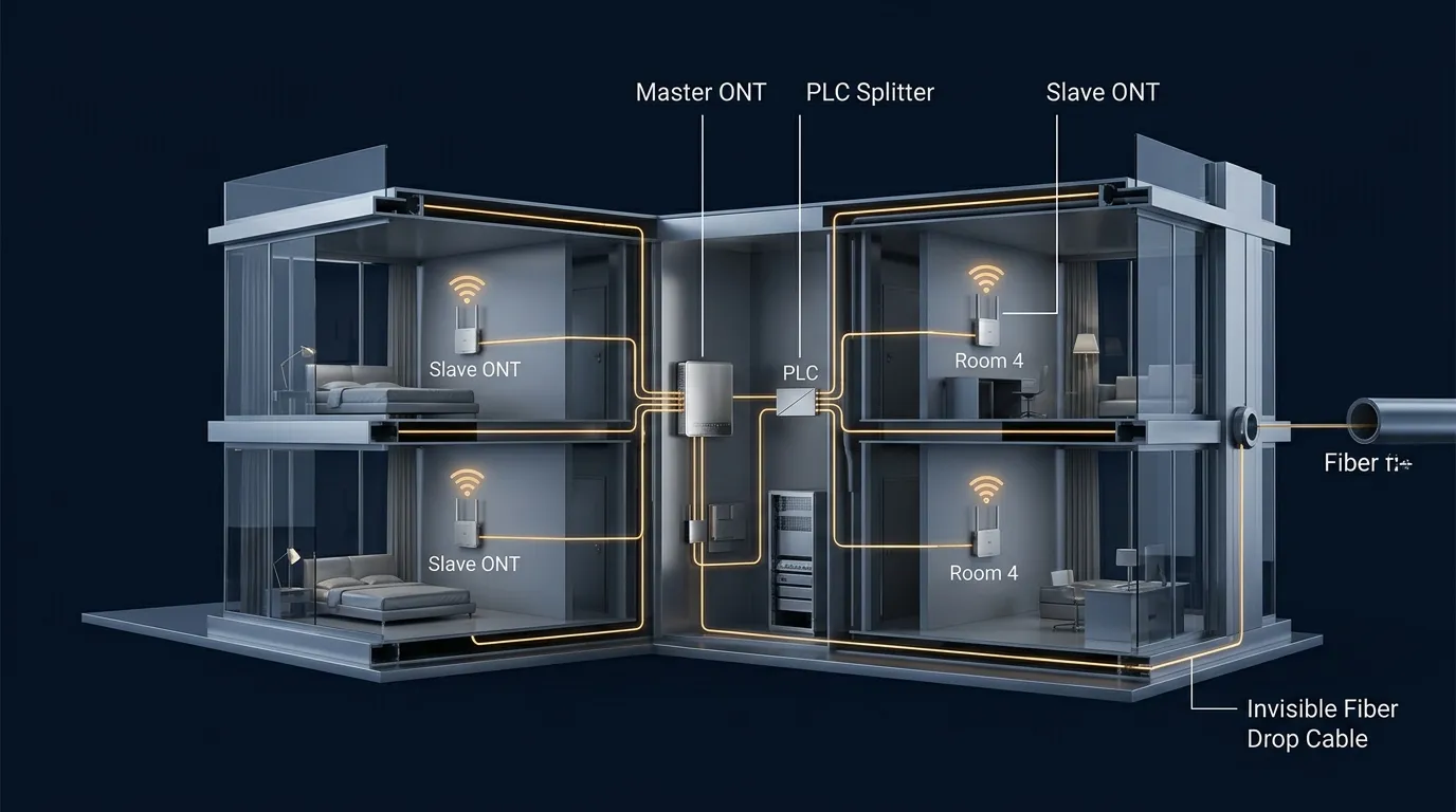
- Master ONT — Installed at the fiber entry point. Connects upstream to the operator's OLT via XGSPON or 10G EPON. Contains a built-in optical splitter or connects to an external one.
- PLC optical splitter — A planar lightwave circuit splitter (typically 1×4, 1×8, or 1×16) that divides the optical signal to feed multiple rooms. Same technology used in FTTH distribution points, now deployed indoors. For a deeper look at splitter types and selection criteria, see our guide to PLC splitters and our PLC splitter product line.
- Fiber drop cables — The physical links from the splitter to each room. Two types dominate deployments:
- Invisible/transparent fiber (G.657.B3 bend-insensitive fiber in a 1–2 mm transparent jacket) for surface-mount routing along baseboards and doorframes. Practically invisible once installed.
- Standard indoor drop cable with LSZH jacket for conduit runs in pre-wired buildings.
- Slave ONT / room AP — A compact unit in each room that terminates the fiber, converts the optical signal, and provides Wi-Fi 6 (802.11ax) plus at least one gigabit Ethernet port. Some models receive power over the same fiber (PoF — Power over Fiber), others use local DC power.
- Wall outlet / termination box — The subscriber-facing interface point, typically with an SC/APC or LC/UPC connector. These fiber wall plates serve the same role as RJ45 wall jacks in copper networks.
- Patch cords and adapters — SC/APC single-mode patch cords connect the ONT to the wall outlet; adapters bridge connector types where needed.
The ITU-T G.fin series (G.fin-SA for the system architecture, G.fin-PHY for the physical layer, G.fin-DLL for the data link layer) standardizes these components and their interfaces, ensuring interoperability across vendors — the same way GPON and XGS-PON standards created a multi-vendor ecosystem for FTTH.
The key architectural insight: once the fiber is in the walls, the network is generation-agnostic. Upgrade from Wi-Fi 6 to Wi-Fi 7? Swap the ONT. Upgrade from XGS-PON to 50G-PON? Swap the OLT and ONT. The fiber infrastructure — with a service life exceeding 30 years — stays in place.
For component manufacturers supplying the passive optical infrastructure — PLC splitters, fiber patch cords, drop cables, connectors, and termination boxes — FTTR represents a meaningful expansion of the market for indoor-grade fiber components, where every room becomes a fiber termination point.
FTTR vs FTTH: What's the Difference?
If you are already deploying FTTH, understanding what changes with FTTR is the fastest path to evaluating it:
Dimension | FTTH | FTTR |
|---|---|---|
Fiber termination point | Single ONT at building entry | ONT + fiber in every room |
In-premises distribution | Copper Ethernet / coax / Wi-Fi | Optical fiber backhaul + Wi-Fi 6 AP per room |
Coverage guarantee | Entry point only | Every room, guaranteed |
Bandwidth per endpoint | Degraded by walls and copper distance | Full fiber line rate to each room |
Component count | 1 ONT, 1 router | 1 master ONT + splitter + N slave ONTs + drop cables + wall outlets |
Infrastructure lifetime | ~10 years (active electronics cycle) | Fiber: 30+ years. Electronics: swappable. |
Deployment complexity | Single-point install | Multi-room fiber routing (pre-wired or retrofit) |
The component count difference matters for procurement. An FTTR deployment for a 4-room apartment requires: 1 master ONT, 1×4 PLC splitter, 4 slave ONTs, 4 wall outlets, and roughly 80–150 meters of invisible fiber drop cable, plus connectors and adapters. If you are in the business of supplying fiber optic passive components, FTTR multiplies the BOM per subscriber. (For a related in-building fiber concept, see our article on FTTD (Fiber to the Desk).)
FTTR vs Mesh Wi-Fi: When Fiber Beats Wireless
A common objection: why not just use a mesh Wi-Fi system? The comparison is worth making directly, because the choice affects architecture decisions for years.
Factor | Mesh Wi-Fi | FTTR |
|---|---|---|
Backhaul medium | 5 GHz or 6 GHz wireless | Single-mode optical fiber |
Signal through walls | 20–50% throughput loss per wall | Zero loss |
Electromagnetic interference | Subject to neighboring APs, microwaves, radar | Immune |
Bandwidth per hop | Halves with each wireless hop (dual-band mesh) | Full bandwidth to every node |
Upgrade path | Replace entire mesh system | Swap ONTs; fiber infrastructure stays |
Installation | Plug and play, DIY | Professional fiber routing required |
Mesh Wi-Fi wins on installation speed. FTTR wins on every technical metric that matters after installation day.
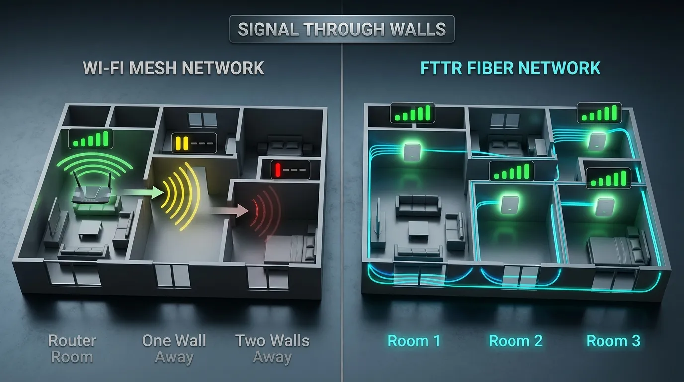
For ISPs deciding what to deploy at scale, the question is not which technology performs better — it is whether the installation cost of fiber routing is justified by the reduction in support calls, churn, and bandwidth-related complaints. GSMA Intelligence noted in a May 2025 analysis that FTTR is "transforming business environments by providing reliable, high-speed internet access" alongside its residential applications — a signal that operator interest spans both market segments.
FTTR Deployment: Pre-Wired and Retrofit
FTTR deployments fall into two scenarios, and the difference determines bill of materials, labor, and timeline:
Pre-wired (new construction) — Fiber conduits are installed during the build phase, alongside electrical. Empty microducts or pre-connectorized drop cables are pulled to each room. This is the lowest-cost, highest-quality path. Several operators in China and Southeast Asia now require FTTR pre-wiring as a standard deliverable in new residential projects, following the model of China Telecom and PCCW.
Retrofit (existing buildings) — Invisible fiber is routed along baseboards, doorframes, and ceiling lines using transparent adhesive. Skilled installers can complete a 4-room apartment in under 3 hours. Where existing conduits are accessible and unobstructed, standard indoor drop cable can be pushed through, avoiding surface-mounted fiber entirely. The constraint is installer skill and conduit condition — not the technology itself.
The Bigger Picture
FTTR is not a standalone technology experiment. It is the in-building access layer of F5G — the same way 5G NR is the radio access layer of 5G. The standards are finalized, the component ecosystem is maturing, and operators in markets from China to Europe are moving from trials to commercial rollouts.
What makes FTTR different from earlier FTTx transitions is that it changes the passive optical component BOM inside the building — not just at the curb or the basement. Every room becomes a fiber termination point, and every termination point consumes connectors, adapters, splitters, drop cables, and wall outlets. For component manufacturers and procurement teams alike, that shift in scale is worth understanding.
For more on FTTR network architectures, component specifications, and deployment guides, visit our FTTR resource hub.