The OSP Project BOM: A Fiber Build Checklist That Survives the Field
An OSP project BOM is where a fiber build's budget is actually decided — and it is almost never treated that way. In most organizations the bill of materials is paperwork: the spreadsheet somebody assembles after the design is signed off, so procurement has something to send out for quotes.
That sequence is backwards, and it is the reason so many outside plant projects finish over budget with a storeroom full of the wrong parts.
Cable price is rarely the culprit. What sinks the number is quieter: cable ordered at design length instead of order length, closure counts guessed from route distance, and a long tail of clamps, anchors, sleeves and lubricant that nobody itemized until a crew was already standing at a pole. None of that is a procurement failure. It's a BOM that was written as a shopping list instead of as an engineering document.
This is the checklist we wish more outside plant (OSP) network builds started from — organized the way the plant is actually constructed, with the quantity math that turns a route map into an order.
What an OSP Project BOM Actually Is
A BOM for an outside plant build is a design output. It is derived, not authored. If you cannot point at the document each line came from, that line is a guess.
Three inputs produce every quantity in a correct OSP BOM:
- The route map — the surveyed path, with each segment classified as aerial, ducted, or direct-buried. This is where linear quantities come from. It only exists after the field walk, easement and permit work that the FOA's outside plant construction reference treats as prerequisites to construction, not as parallel tasks.
- The splice diagram — which fibers terminate where, at which closure, in which tray. This is where closure, sleeve, pigtail and tray quantities come from.
- The optical loss budget — the total allowable attenuation between the OLT and the last subscriber. This constrains how many splices, connectors and splitter stages the design can afford, which in turn constrains the BOM. Run it before you buy, not after: a link loss budget that fails at the design stage is cheap to fix, and expensive once the reels are on site.
Change any of the three and the BOM changes. That is the whole point. A BOM that can be written without them is a catalog order, not a bill of materials.
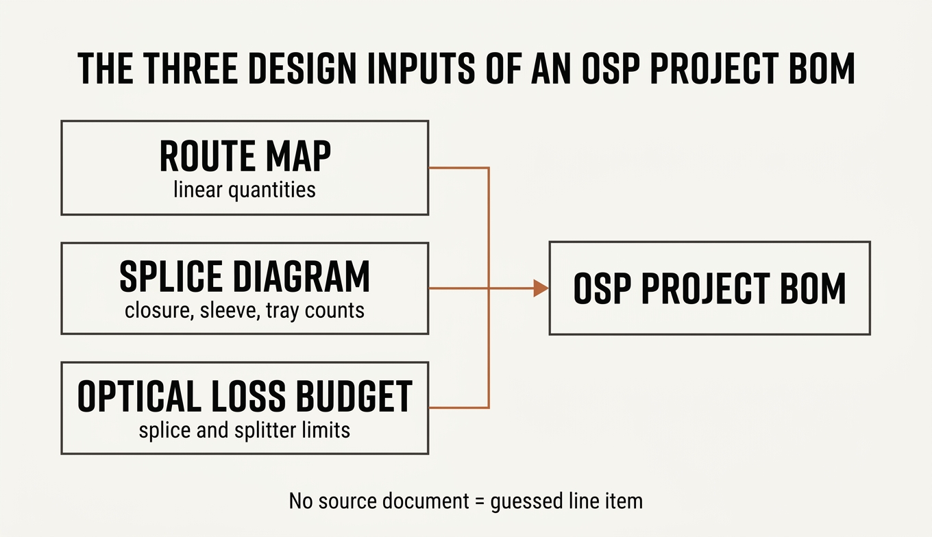
The three design documents every BOM quantity must trace back to. If a line item has no source, it was guessed.
BOM vs. bill of quantities — they are not the same document
These get used interchangeably and they shouldn't be.
A bill of quantities (BOQ) answers how much work. It is measured in trench-meters, pole-sets, splice-points, restoration square-meters — the units a contractor prices labor against.
A bill of materials (BOM) answers what to buy. Every line is a purchasable item with a manufacturer specification, a unit of measure, and a quantity that already includes waste and slack.
The two overlap and must reconcile — 3,200 meters of trench in the BOQ had better correspond to conduit, warning tape, tracer wire and marker posts in the BOM — but a BOQ line cannot be sent to a supplier and a BOM line cannot be given to a crew as a work order. Projects that merge them end up with a document that serves neither.
One more distinction worth naming: a vendor's BOM configurator is not this document either. Those tools are scoped to one manufacturer's catalog, which makes them useful for filling in part numbers and useless for telling you that you forgot tracer wire.
The BOM, Layer by Layer
Organize the BOM by how the plant gets built, not by how a supplier's catalog is indexed. Crews work in layers; a BOM that mirrors those layers can be checked against the field, and gaps become visible.
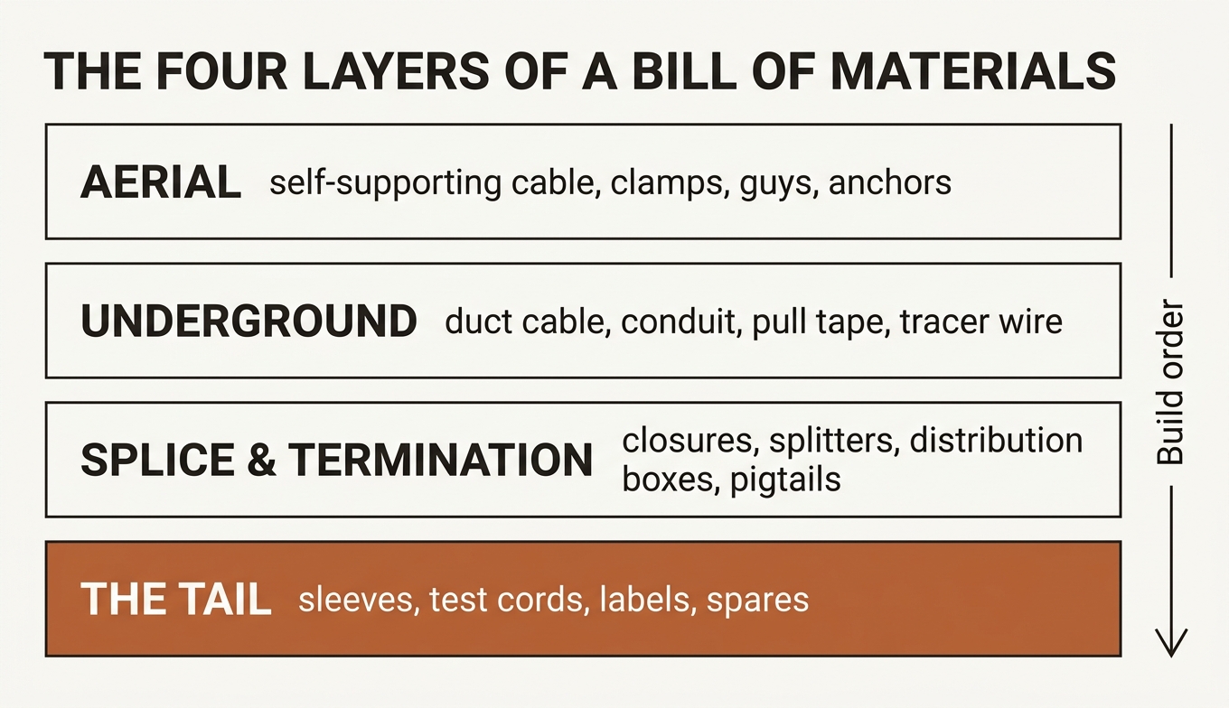
Structure the BOM the way the plant is constructed. Each layer has a distinct failure mode when it is under-specified.
Four layers, in build order.
Layer 1 — Aerial
Aerial plant is cheap to install and expensive to get wrong, because the cable's mechanical envelope has to survive spans, ice, wind and — on joint-use structures — an electric field.
There are two aerial strategies, and they generate completely different hardware lists. Either the cable carries itself, or you string a messenger and lash the cable to it. Pick one before you write a single line.
Line item | The spec that must appear on the BOM | Why it gets missed |
|---|---|---|
Self-supporting cable | Fiber count, span length, sheath rating, strength member | Ordered on fiber count alone |
Messenger / lashing wire | Grade, diameter, lashing wire spool length | Assumed to be "the contractor's" |
Dead-end clamps | Cable OD range, per-terminal-and-corner-pole count | Counted per pole, not per attachment |
Suspension clamps | Cable OD range, tangent pole count | Same |
Down guys, anchors, guy grips | Soil class, tension load | Only shows up in the BOQ |
Pole hardware, storage brackets | Attachment type, slack-loop bracket count | Forgotten until slack is spec'd |
Cable markers, aerial warning signs | Spacing per local code | Left to "site supply" |
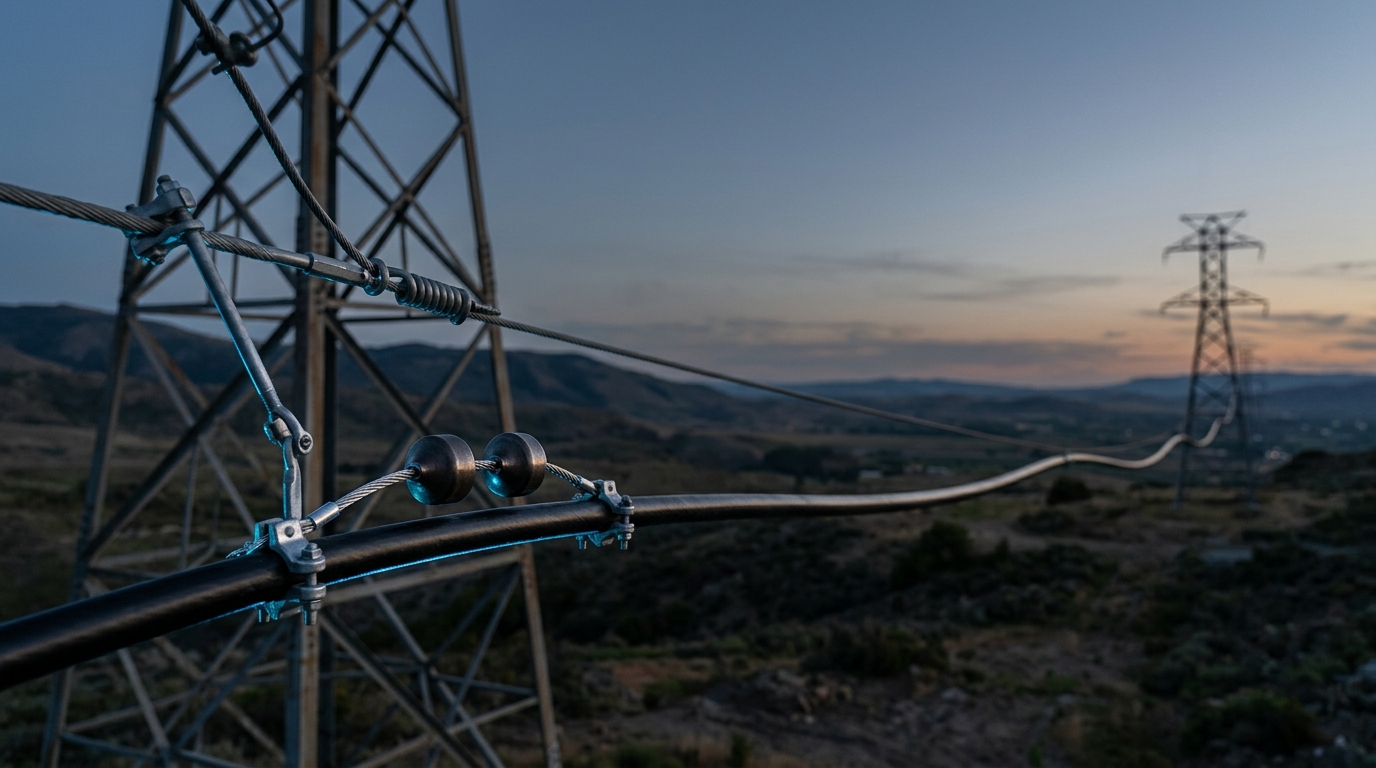
The line that deserves the most attention is the first one. On an ADSS self-supporting cable, span length is not a nice-to-have on the BOM — it is the parameter the cable is built around. Longer spans require more aramid yarn to hold tension, which raises cable weight, which changes the clamps you need and the load the pole sees. And where the route runs on transmission structures, the electric field decides the sheath: TTI Fiber's ADSS is supplied with a standard PE jacket at distribution voltages up to 35 kV and a track-resistant (AT) jacket for 110–220 kV lines, across 2–576 fibers and spans reaching 880 m, per the manufacturer's 2024 catalog. Specify "48-core ADSS" without the span and the voltage class and you have not specified a cable.
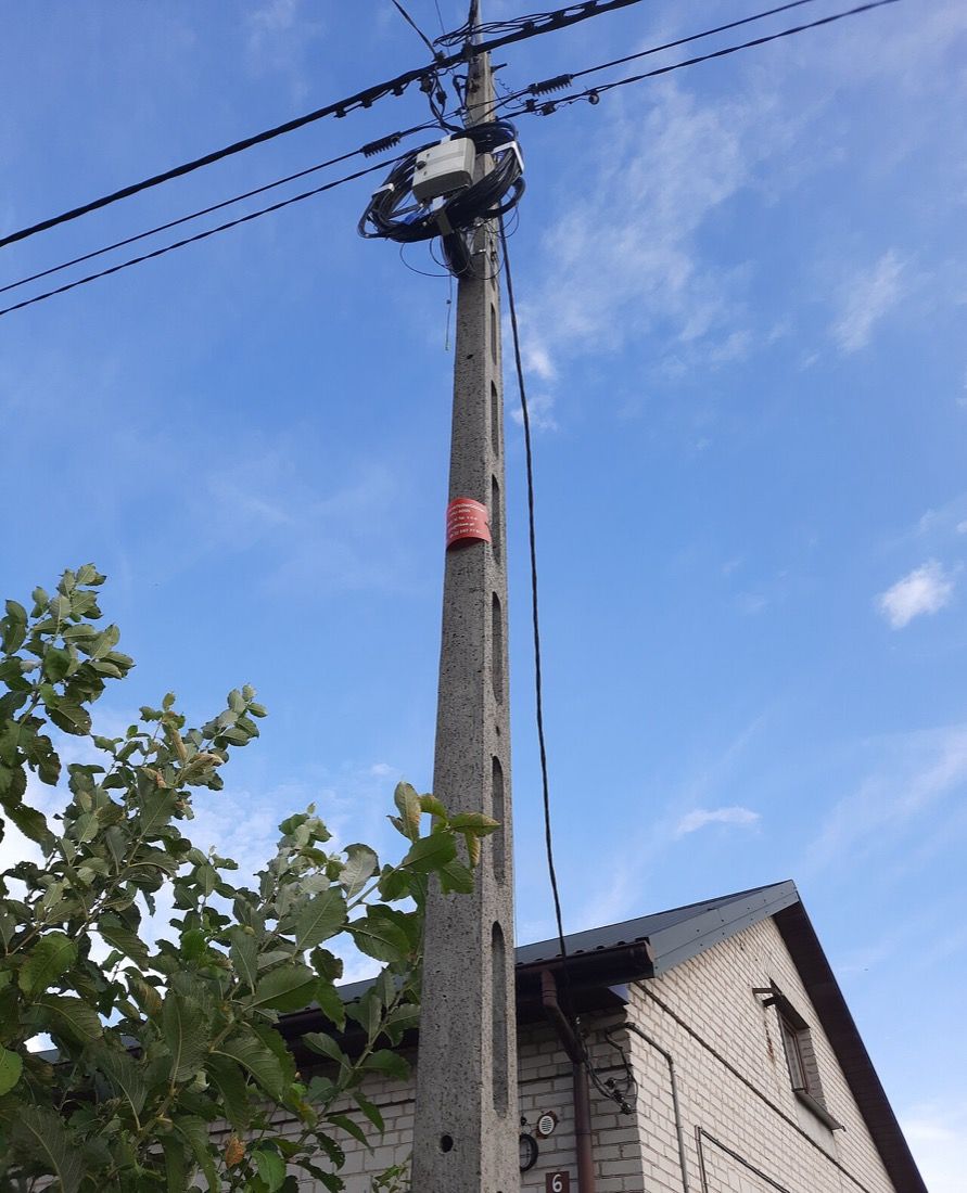
One pole, four BOM lines: the ADSS cable, the pole-mounted closure, the attachment hardware, and the storage bracket holding that slack loop. The loop is meters of cable that exist on the reel and not on the route map.
If the route is on transmission towers, the choice between a dielectric self-supporting cable and an optical ground wire is a power-engineering decision that precedes the BOM entirely — we walk through it in ADSS vs OPGW. It is out of scope for this checklist.
Note also that the aerial layer is where slack lives. FOA's aerial installation guidance treats storage loops as standard practice, and every stored loop needs a bracket on the BOM.
Layer 2 — Underground
Underground work is the opposite: expensive to install, forgiving of a slightly over-specified cable, and utterly unforgiving of a missing consumable, because you cannot re-open a trench for a spool of pull tape.
The cable choice here follows the installation method, not the fiber count. Whether the segment is buried, ducted, or aerial decides the armor construction that belongs in the row — and the FOA's underground construction reference is a useful sanity check on which method your route actually requires.
Line item | The spec that must appear on the BOM | Notes |
|---|---|---|
Duct / direct-burial cable | Fiber count, armor type, water blocking, rodent protection | See selection table below |
HDPE conduit / innerduct | OD × wall, coil length, color coding | Coil length drives coupler count |
Microduct + air-blown microcable | Duct bore, cable OD, blowing distance | Only if the route is air-blown |
Pull tape / pull rope | Rated tension, length = duct length + pulling allowance | Ordered short more often than any other item |
Cable lubricant | Volume per duct-meter and cable OD | Frequently absent entirely |
Duct rodder, duct plugs, couplers | Duct OD | Plugs are per duct-end, not per duct |
Warning tape | Depth per local code, roll length | — |
Tracer wire + access points | Gauge, splice kits | Mandatory with dielectric cable — a non-metallic cable is invisible to a locator |
Route markers / marker posts | Spacing per standard | — |
Handholes, pull boxes, manholes | Load rating, spacing | Spacing is a design decision, not a default |
Bonding and grounding kits | Per armored-cable entry, per cabinet | Skipped when the cable is dielectric — correctly — then skipped again when it isn't |
For the cable row itself, the practical mapping:
Segment condition | Cable family | What it buys you |
|---|---|---|
Duct, standard | GYTS — stranded loose tube, corrugated steel tape | Crush resistance, 2–216 fibers |
Duct, weight- or moisture-sensitive | GYTA — APL moisture barrier | Lighter than GYTS with a better moisture barrier |
Direct burial | GYTA53 — double armor, double sheath | Survives backfill and ground movement |
Lightning-prone or power-line corridor | GYFTY — non-metallic strength member | No metallic path to conduct a strike |
Rodent territory | SLTN RP — glass-yarn rodent layer, dry core | Rodent protection without steel |
Air-blown microduct network | GCYFTY — stranded microcable, 12–288 fibers | Density in small bores |
Whatever the family, the specification line must carry the fiber grade. ITU-T G.652 single-mode fiber is the default for OSP; writing "SM" and stopping there leaves the bend performance and the attenuation ceiling unstated.
Layer 3 — Splice, Termination and Distribution
This is the layer where quantities stop being linear and start being combinatorial — every closure implies trays, every tray implies splices, every splice implies a sleeve.
Line item | Quantity driven by | The spec that must appear |
|---|---|---|
Reel length and splice diagram — not route distance | Fiber capacity, port count, dome vs. inline, seal type | |
Splice trays | Closure capacity | Fibers per tray |
Heat-shrink splice sleeves | Total fusion splices + spares | Length, fiber count |
Service area subdivision | Port count, ingress rating, splitter slots | |
Optical termination boxes / ODF | Terminated fiber count | Rack units, adapter type |
PON split ratio | Ratio, package (bare / steel tube / LGX / rack), insertion loss | |
Pigtails | Terminated fibers per box | Connector type and polish |
Patch cords | Cross-connect count | Length, connector pair, insertion and return loss |
Adapters | Port count | Simplex / duplex, sleeve material |
Street cabinets / pedestals | Distribution architecture | Enclosure rating, mounting |
Two specification traps hide in this table.
Closures are chosen by capacity band and re-entry method, not by fiber count alone. A closure that can hold your splice count today but cannot be reopened without a new heat-shrink kit will cost you every time the network is extended. Mechanical-seal closures are re-enterable; heat-shrink versions consume a kit per entry. The dome closures we build span 12–288 fibers with an IP68 rating tested at 1.5 m for 24 hours — capacity, seal type, ingress test condition. That is what a closure line looks like when it is properly specified. If you are still deciding, we break the families down in splice closure types.
Splitters have a loss budget consequence, so they have a BOM consequence. A 1×8 PLC splitter with a typical insertion loss around 10.2 dB and a maximum near 10.5 dB — within the performance envelope that ITU-T G.671 defines for passive optical components — is usually the single largest loss element in a PON link. Each doubling of the split ratio adds about 3 dB of splitting loss, so 1×8 to 1×32 is a fourfold split and roughly 6 dB in theory; real datasheets, which fold in accumulating excess loss, put the 1×8-to-1×32 delta closer to 7 dB. That has to come from somewhere, and it usually comes out of the splice budget. The split ratio is a network decision that lands in the BOM as splitter count, port count and pigtail count all at once.
Finally, the drop layer. FTTH drop cable quantities are per-subscriber, which makes them the easiest to model and the easiest to under-order, because the take rate you plan for is not the take rate you build for. A self-supporting drop cable with an integrated steel messenger — our GJYXCH is rated for aerial spans up to 80 m and ships on reels up to 4 km — lets one cable run from the pole through the wall without a transition splice at the entry point. That removes a component, a labor step and a failure point from the BOM at once.
Layer 4 — The Tail
The tail is where BOMs quietly fail. Every item below is small, cheap, and capable of stopping a crew.
- Fusion splice consumables — cleaver blades, electrodes, alcohol, wipes, protection sleeves beyond the splice count
- Test and acceptance — OTDR launch and receive fibers, reference cords, connector inspection consumables, cleaning supplies
- Labelling and documentation — cable tags, closure labels, tray labels, as-built printing
- Safety and site — pole steps, warning signage, traffic control consumables
- Spares — the closure, the splitter and the drop cable you will need on day one of maintenance
Two of these deserve a rule rather than a bullet. Splice sleeves should be ordered against total splice count plus a spares allowance, because a failed splice consumes a second sleeve. And every OSP project should carry a maintenance spares line in the BOM itself, not in a separate document that gets deprioritized when the budget tightens.
Turning Route Miles Into Quantities
Here is the part no competing article covers, and it is where the money is.
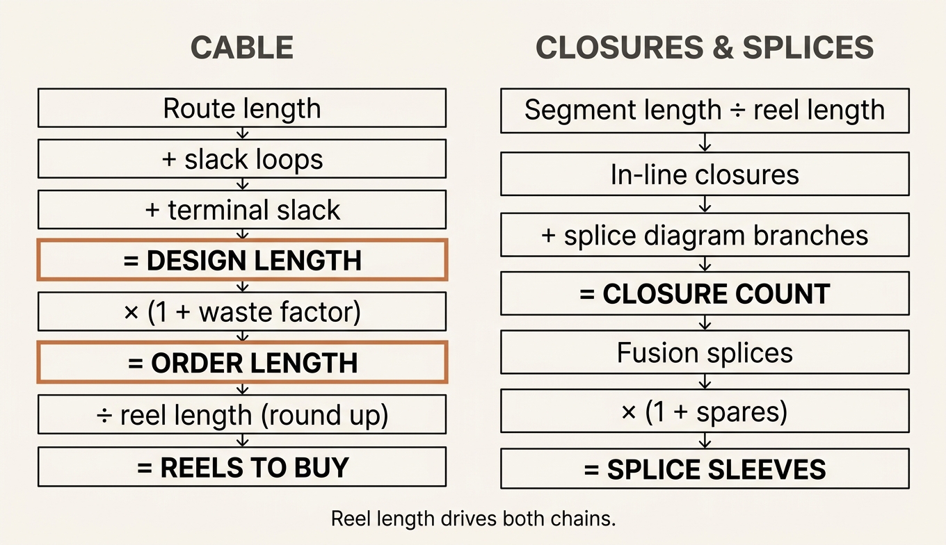
Design length is not order length. Two derivation chains produce every quantity that matters.
Cable: design length is not order length
The mistake is ordering the number on the route map. The correct chain:
route length (per segment, per installation method) + slack loops (storage at poles, handholes, and every closure) + terminal slack (cabinet, OLT room, splice trailer working length) = design length × (1 + waste factor) (pulling losses, cuts, damaged ends) = order length ÷ reel length (rounded UP to whole reels) = reels to purchase
Four things fall out of that chain that people miss.
Slack is a line item, not a rounding error. Every closure needs enough cable to reach a splice trailer and come back. Every pole storage loop and every handhole loop is meters of cable that exists on the reel and not on the map. The values are set by your operator's construction standard — not by a blog post — so pull them from that document and put them in the spreadsheet as an explicit column. What matters is that the column exists.
Waste factor is a contingency, not a fudge. Pulling underground cable through duct damages ends; FOA's underground installation guidance describes the tension and lubrication practice that limits it. Complex routes with many pull points warrant more contingency than simple ones. Again: your standard sets the number. The failure is not choosing 5% instead of 8% — it's having no column at all.
Reel length rounds up, and the remainder is not free. If a segment needs 5.2 km and the cable ships on 4 km reels, you buy two reels and carry 2.8 km of stock. That stock either becomes another segment's cable or becomes a write-off, and which one it is depends on whether you planned reel allocation across segments before ordering. Reel and drum lengths vary by cable family and by manufacturer — check the product datasheet rather than assuming a standard.
Reel length also drives closure count — which brings us to the second chain.
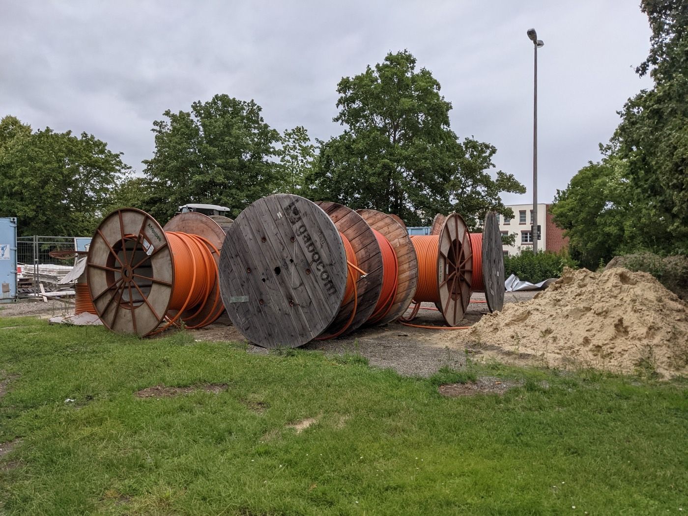
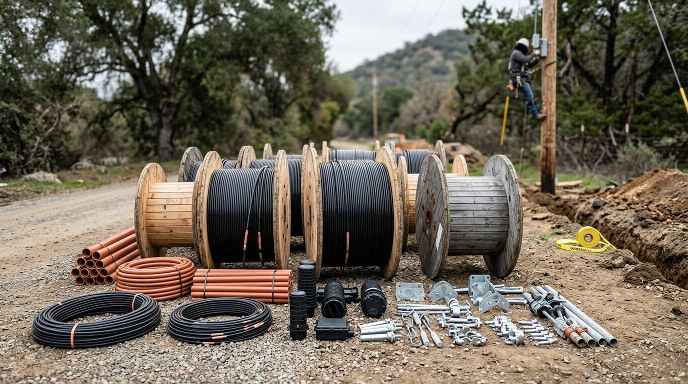
Every drum on this site is a purchase decision that already happened. How much cable is on each one determined how many closures, splices and sleeves the BOM had to carry.
Closures and splices: driven by reels, not by distance
The single most common quantity error in an OSP BOM is computing closure count from route length divided by some assumed spacing.
Closures exist where cable ends meet. Cable ends exist where a reel runs out. So — using the whole-reel count you already rounded up in the cable chain, not a fresh division:
closures ≈ (reels on the segment − 1) [in-line splice points] + closures required by the splice diagram [branches, taps, drops] + closures at every access point the design specifies
Two guardrails on that first term. Take the rounded-up reel count — 5.2 km on 4 km reels is two reels and one in-line splice, not 5.2 ÷ 4 − 1 rounded to zero. And a reel-end splice has to land in an accessible structure — a handhole, a pit, a pole — never mid-duct, so the splice diagram and the route drawing have to agree on where those ends fall.
Then, and only then:
fusion splices = Σ (fibers spliced at each closure) ← read off the splice diagramsplice sleeves = fusion splices × (1 + spares allowance)splice trays = ⌈fibers per closure ÷ tray capacity⌉
The consequence is counterintuitive and worth stating plainly: buying cable on longer reels reduces your closure count, your splice count, your sleeve count, and your splicing labor. Reel length is a procurement decision that propagates into four other BOM lines and into the schedule. Very few BOMs are built in an order that lets you see this, which is exactly why we recommend the layer structure above — the cable row and the closure row sit close enough together to notice.
Splitters and drops: driven by architecture
splitters = homes passed ÷ split ratio (per distribution point)FDB ports = splitters × output ports + spare portsdrop cables = homes connected × (1 + rework allowance)pigtails = terminated fibers per boxpatch cords = cross-connects at the cabinet and the OLT
Homes passed and homes connected are different numbers, and the BOM needs both. Feeder cable, splitters and distribution boxes size to homes passed. Drop cable, subscriber terminals and drop hardware size to homes connected — which is take rate, which is a commercial forecast, which is the one input in this entire document that engineering does not own. Flag it, date it, and note whose number it is.
A Procurement-Ready BOM Structure
A BOM that procurement can quote against and a crew can receive against needs one discipline: one row equals one purchasable item. Not one row per category, not one row per drawing symbol.
Column | What it holds | Why it earns its place |
|---|---|---|
Item ID | Sequential, stable across revisions | Revisions are inevitable; renumbering breaks quote comparisons |
Layer | Aerial / Underground / Splice / Tail | Makes gaps visible at a glance |
Description | Plain-language item name | The crew reads this column |
Specification | Fiber count, grade, armor, sheath, span, rating, standard | The column that decides whether you got what you designed |
Standard | IEC 60794, IEEE 1222, Telcordia GR-20, GR-771, TIA-758 | Gives the supplier an acceptance criterion |
Unit | m / each / reel / roll / kit | "1 cable" is not a quantity |
Design qty | From the route map or splice diagram | Traceable |
Slack / waste | Explicit, per your construction standard | The column most BOMs omit |
Order qty | Design + slack + waste, rounded to purchase units | The number that goes to the supplier |
Source document | "Route map rev C, segment 4" | Every line traces to a design document |
Lead time | From the supplier | Long-lead items drive the schedule, not the budget |
Three rules make the structure hold up:
The specification column is the deliverable. "ADSS, 48F" is not a specification. "ADSS, 48F, G.652.D, 250 m max span, AT jacket, IEEE 1222" is. Everything upstream of procurement is an argument about that column.
Every line traces to a document. If a row's source column is empty, someone guessed. Guesses are allowed — engineering runs on them — but they must be visible so they can be checked later.
Long-lead items get flagged before quantities are final. Custom-length pre-terminated assemblies, non-standard fiber counts and specialty jackets have lead times measured in weeks. A BOM that is quantitatively perfect and two months late is a failed BOM.
Five Mistakes That Blow the Budget
1. Ordering design length instead of order length. The route says 5.2 km, so 5.2 km gets ordered. No slack, no waste allowance, no reel rounding. The crew runs short somewhere in the last kilometer and the project buys an emergency reel at an emergency price. This is the single most expensive line-item error in outside plant work, and it is arithmetic.
2. Counting closures by distance. Closure spacing is not a constant. Closures land where reels end and where the splice diagram says fibers branch. A BOM that assumes "one closure every 2 km" will be wrong in both directions — over-ordering on long-reel segments, under-ordering wherever the design has taps.
3. Specifying cable by fiber count. "144-core armored" tells a supplier almost nothing. Missing: fiber grade, armor construction, water blocking, rodent protection, sheath material, and — for anything self-supporting — span length and voltage class. Two cables matching that description can differ by a factor of two in price and can differ in whether they survive the route at all.
4. Losing the hardware tail. Dead-ends, anchors, guy grips, tracer wire, marker posts, duct plugs, pull tape, lubricant, splice sleeves, cleaver blades. Individually trivial. Collectively they are the reason a fully-provisioned crew stands idle. The tail is small money and large schedule risk, which is the worst combination to discover in the field.
5. Letting the BOM drift from the splice diagram. The design gets revised — a branch moves, a cabinet relocates, a split ratio changes — and the BOM is not re-derived. Now the closure count reflects revision B and the splice diagram reflects revision D. Reconcile the two documents at every design revision, and treat any BOM whose source column doesn't cite a revision number as unreconciled by default.
Where to Start
Take your route map, your splice diagram and your loss budget. Build the four layers. Add the slack and waste columns before you add quantities, so the discipline is structural rather than remembered. Reconcile against the splice diagram at every revision.
Then, before the order goes out, check the one thing procurement cannot check for you: whether the specification column says enough that a supplier could not deliver something technically compliant and functionally wrong.
That last column is where a manufacturer earns their place. TTI Fiber builds outside plant cable, closures, distribution boxes and splitters in one vertically integrated plant, which means the span length, jacket class and reel length on your BOM can be engineered against your route rather than picked from a catalog. If you have a route map and a fiber count, send us the segment details and we'll come back with the specification lines — reel allocation included — within 24 hours.