Fast Connector vs Fusion Splicing in FTTH
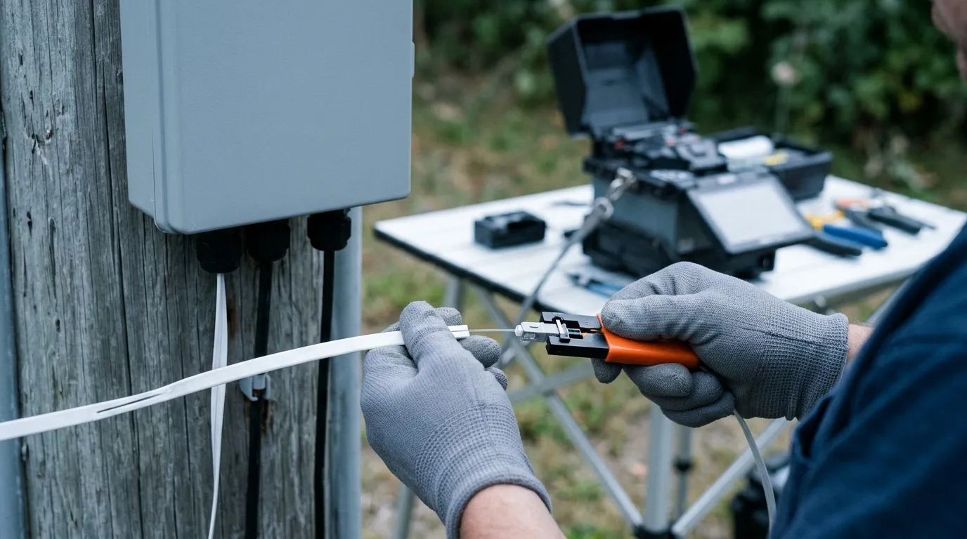
Two crews, same subdivision, same drop count. One hauls a splicer, a battery, a cleaver and a box of pigtails to every house. The other carries a belt pouch and a box of field-installable connectors. Both finish, both pass acceptance. One spent capital before the first drop went live; the other spends a few dollars more on materials and wins back one to seven minutes on every drop. Which dominates is what the fast connector vs fusion splicing decision hangs on.
Fast connector or fusion splicing on the drop: pick on visits and location, not on loss. Connectors for confined boxes, re-terminations and fiber cut short of the enclosure; pigtail-plus-fusion wherever the count, the closure or the permanence decides.
Most pages never reach that question. They compare a bare fusion joint at 0.05 dB with a terminated connector at 0.3 dB and let you conclude that splicing is ten times better. It is better — at the joint, not at what you buy, which is a connector on the end of a cable. The last-mile fiber access guides cover the design; this page starts where it ends.
Fast Connector vs Fusion Splicing: The Comparison Is Framed Wrong
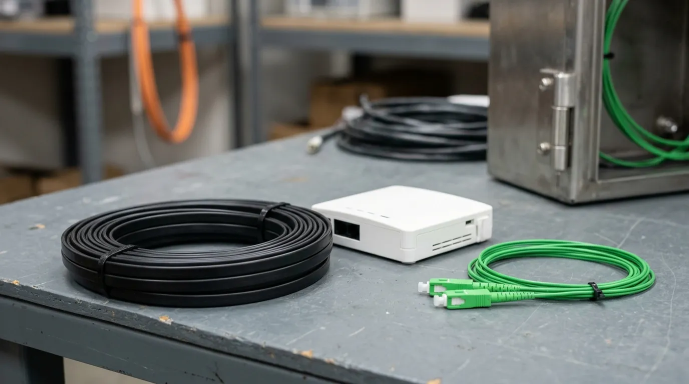
A fusion splicer joins two cleaved fiber ends with an electric arc. It has no mechanism for putting a connector on a cable. To terminate with one you add a second operation: splice a factory pigtail onto your cable, connector already polished on the far end. The Fiber Optic Association's outside-plant termination reference treats that as normal practice — "most field singlemode terminations are made by splicing a factory-made pigtail onto the installed cable rather than terminating the fiber directly."
The honest comparison, then, is pigtail plus fusion splice against field-installable connector. The first gives a factory end face and a splice you had to make: two loss elements, one the machine can measure. The second gives a factory end face and a splice you also had to make — a pre-polished ferrule with a short stub, your cable fiber meeting it in a mechanical splice held in a V-groove with index-matching gel. You are making a mechanical splice. You are just making it inside a connector.
Option | What the crew does on site | What the loss figure describes | Where it belongs |
|---|---|---|---|
Fast (field-installable) connector | Strip, clean, cleave, seat, lock, VFL check | A mated connection, internal splice included | Drops, repairs, cramped boxes, no power |
Pigtail + fusion splice | Strip, clean, cleave, arc, sleeve, coil into tray, plug | The splice plus the factory connector | Closures, ODFs, cabinets, high counts |
Pre-terminated cable | Pull, route, plug | The factory connector only | New builds with known lengths |
Bare mechanical splice versus fusion splice is a different decision, at a different layer — a joint, not a terminated end — and this page does not cover it. Everything below is about what sits at the end of the drop.
What Each Method Actually Puts in the Loss Budget
Insertion loss is not the property of a connector on a bench. It is the loss of a mated pair, measured against a reference connector by the method fixed in IEC 61300-3-4. The FOA adds the half that matters: for a termination made by splicing a connector onto a fiber, "the connection loss of this type of termination includes the typical connection loss tested when mated to a reference connector plus the splice used to attach the connector to the fiber." The splice is already inside the number.
Which is why three figures that look comparable are not:
- 0.15 dB is the FOA planning value for a single-mode fusion splice in a loss budget — two fibers joined, no connector anywhere.
- 0.75 dB is the TIA-568 connection-loss ceiling, deliberately loose so prepolished and splice-on connectors can pass — a whole terminated end, mated.
- A 0.3 dB factory-polished connector is that same kind of quantity. Putting a bare joint beside a terminated end flatters fusion by roughly the loss of the connector the joint does not have.
The floor comes from an air gap: light crossing into air and back loses about 5 % to Fresnel reflection, so no connector with an air gap comes in under about 0.3 dB. Polishes crush that gap, which means the polish grade, not the termination method, sets return loss. Field numbers follow the cleave — a precision cleaver holds these connectors near 0.5 dB, a simple one drifts toward 0.75 dB. Fujikura's FAST connector series quotes the same 0.5 dB average with a return loss of 40 dB or more — PC-grade reflectance, not the ≥50 dB a UPC part is specified to, and nowhere near what APC brings. That is adequate for data and thin for a drop carrying an analog video overlay.
Now the arithmetic on a real drop:
- 300 m of single-mode at 0.4 dB/km at 1550 nm: 0.12 dB.
- One 1:32 splitter: whatever it takes, per the splitter loss explainer. It usually dominates the list, and the ITU-T G.984.2 budgets are what the design must fit inside.
- Fast connector at the ONT, internal splice included: 0.5 dB average, 0.75 dB at the TIA ceiling.
- Pigtail plus fusion splice, connector included: 0.15 + 0.3 = 0.45 dB typical, and 0.15 + 0.75 = 0.90 dB when the connector is taken at that same ceiling.
Compare like with like, which is the whole point of the section above. On the typical basis the fast connector is 0.05 dB behind. On the ceiling basis it is 0.15 dB ahead: 0.75 against 0.90, because the pigtail route carries a connector too and that connector can miss its polish just as easily. So the gap on one drop is a rounding error in one direction and a couple of tenths in the other — and neither decides whether the OLT-to-ONT link passes on a short subscriber drop built from flat or round drop cable. What decides it is the closure and the trunk, where 0.3 dB repeats ten times. That is the real reason fusion owns the outside plant, and it is not the reason usually given.
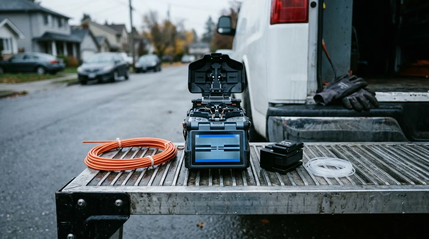
What buying a splicer actually puts on the tailgate: the machine, its cleaver, the protectors, and a flat surface that must be level and out of the rain.
Tooling: What the Splicer Costs Before the First Termination
A live price band, not a remembered one. On 22 November 2026 a distributor listing for fusion splicers carried 45 products; the first twelve — core-alignment kits with cleavers, active-clad kits, machine-only units from three manufacturers — ran from $3,417.00 to $12,739.50. A mid-range core-alignment kit with a cleaver sat at $7,840.00. USD list, before tax, and it moves.
The machine is not the whole capital item: add electrodes with a finite arc count, spare blades, protectors, a battery that ages, calibration, and something to put it on when the ground is wet. The connector side needs a cleaver, a stripper, wipes and a visual fault locator — low hundreds of dollars, most of it already in the van.
The splicer is capital shared across every enclosure a crew touches; a connector is a consumable charged to every drop. Those amortize in opposite directions, which is why "fusion wins above a dozen fibers" gets repeated without ever being derived.
So derive it. Let C be splicer capital, p the per-drop consumable premium of a fast connector over a pigtail plus protector, and L*r the per-drop labor difference at crew rate r. Payback on consumables alone is n = C / (p - L*r), and it exists only when p exceeds L*r.
Put plausible numbers in, labeling every one of them as an assumption rather than a measurement: C = $7,840, the mid-range kit priced in the section above; p between $3 and $5; r = $60 per crew-hour, which is exactly $1 per crew-minute; and L between 1 and 7 minutes — a fast connector assembles in one to two minutes, a pigtail plus splice takes three to eight (broken down in the next section), so the difference runs from 3 − 2 at the best corner to 8 − 1 at the worst. That puts L*r between $1 and $7, so the denominator p - L*r runs from -$4 to +$4.
That range is the finding, not a rounding problem. The denominator is positive only in the top corner of it — a high premium against a small time difference — and there break-even is 1,960 to 7,840 drops: 7,840 / $4 at the best corner, 7,840 / $1 at the weakest point that still qualifies. Across the rest of the band it reaches zero and then goes negative, and a negative denominator means the connector route is already the cheaper way to buy a drop — so no drop count pays the machine back at any volume.
On a 400-drop extension, then, the splicer does not pay for itself out of connector savings. It pays because it is the only way to make the splices on the feeder and distribution side, where no connector alternative exists — and once it is on the truck for that reason, using it on a drop costs almost nothing extra. What does not hold is any claim that the crossover is a fixed fiber count.
Cycle Time and Rework: Where the Money Actually Goes
Per-termination seconds are what everyone argues about and what matters least. A fast connector is strip, clean, cleave, seat, lock, test: one to two minutes. A pigtail plus splice runs the same sequence and then adds arc, protector and coiling into a tray without breaking bend radius — three to eight minutes per fiber, the range this page assumes, which is twenty to fifty-three crew-hours across 400 drops. The 1-to-7-minute difference between the two is the L in the arithmetic above. Real money, not transformative.
What is transformative is the visit. A splicer must be carried, powered, sheltered from rain and set on something level; in a stairwell or at the top of a pole that is often impossible, and the job moves to a second appointment. The labor case for fast connectors is not seconds per termination — it is the second visit it does not need, and on a residential estate a callback costs more than a day of splicing.
Rework makes the same argument from another direction. Almost every comparison page has a rework sentence; almost none has a rework rate, which is odd, because on a large build the rework bill exceeds the connector bill. The failure modes are few and shared — a bad cleave, a contaminated end face, short insertion leaving an air gap and its 0.3 dB Fresnel penalty, the wrong polish — and cleave quality dominates.
What differs is when you find out. A fusion splicer estimates the loss of the splice it just made and refuses to proceed on a bad cleave: the failure self-reports, before the protector goes on, and the fix is one re-cleave and one more arc. A fast connector is silent. The joint sits inside an opaque body with no read-out, so a marginal cleave surfaces at acceptance test — after the box is closed, after the ladder is down, often after the crew has left the street — and the fix is a new connector, because the old one is scrap.
That asymmetry is the strongest technical argument for fusion at the joint, stronger than the loss argument. It is also one a connector program can neutralize by inspecting every termination rather than sampling: a visual fault locator catches gross insertion failures, a power meter or an OTDR catches the rest. The termination procedure and its inspection step is where that discipline lives.
Model it with illustrative yields, not survey data. At 95 % first-pass, 400 drops produce 20 re-terminations; at 90 %, forty. If each needs a return visit rather than eight minutes on site — an hour a visit once travel, access, re-termination and retest are counted, an assumption, not a measurement — that is twenty to forty crew-hours, or two and a half to five crew-days. The rework bill is set by where the rework happens, not by how many failures there are.
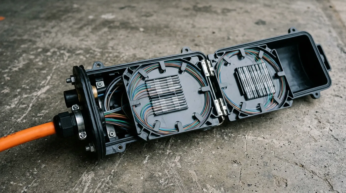
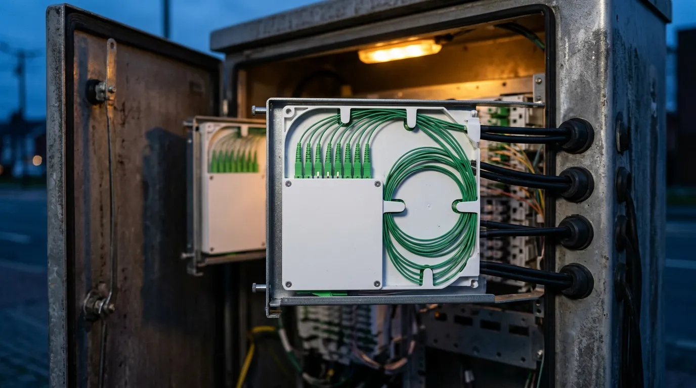
Where fusion earns its capital: a tray of splices at a fiber count no connector field would want to handle, each measured by the machine that made it.
Environment: Dust, Rain and the Closure You Cannot Kneel In Front Of
Location eliminates methods faster than any cost model. A sealed closure on a pole six meters up, with a tray stack and a bend-radius budget, is fusion territory. A 300 mm wall box at chest height in a stairwell, drop already glanded in and the customer waiting, is connector territory: nowhere to stand a splicer, nowhere for a battery, no light.
The framework behind "harsh environment" is more specific than the phrase. IEC 61753-1 defines the service categories for passive fiber products — C for controlled, OP and OP+ for outdoor protected, I for industrial, A, G and S for harsher housings — and since 2018 it covers field mountable connectors and mechanical splices as product types. It also fixes mating-durability severity in the first four categories at 200 cycles for cylindrical ferrules. That is the number to write into a specification, because it is what the standard tests. Whether the box is IP67 or IP68 is its own decision, covered in the ingress-rating comparison, and a dome closure, an inline closure and a cabinet each impose their own tray count, working height and weather exposure.
Fusion's weakness is not the joint, which is glass; it is everything around it. The arc chamber and the cleave both have to be clean, and an arc struck in wind, rain or dust produces a marginal splice or none. The connector's weakness is the gel interface and the clamp: a fused joint has no moving parts and no polymer at the optical interface, a mechanical joint has both, and both see every thermal cycle the enclosure sees. Indoors that has not been a problem; exposed on an aerial closure across ten years it is a real difference, and it is why the outside plant stays fused.
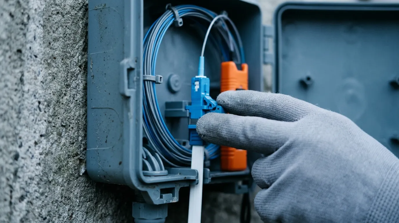
The location that decides the method: a box you cannot kneel in front of, on a wall you cannot put a splicer against.
The Decision Table
Situation | Method | Why |
|---|---|---|
House drop, wall box, no power | Fast connector | No splicer to carry; one visit |
MDU riser, 24 drops in one visit | Fast connector | Speed compounds; no tray per flat |
288-f feeder into a pole closure | Fusion splice | Fiber count; no connector in the joint |
Splitter ports in a street cabinet | Fusion splice | Density; loss repeats per port |
Dig-up repair at 02:00 on a live trunk | Fusion, or a mechanical splice now and fuse later | No headroom to give away |
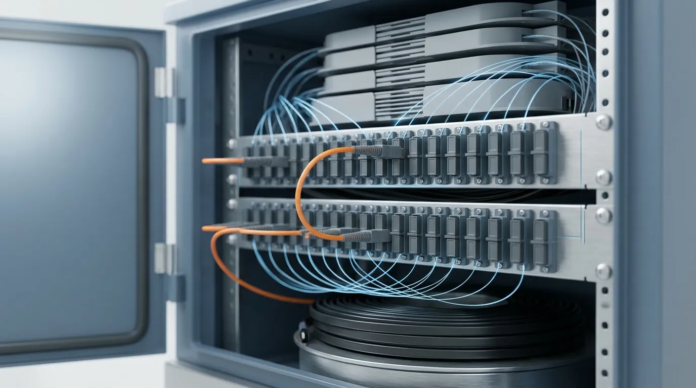
ODF in a central office | Fusion onto pigtails | Every fiber tested and documented |
Drop with an analog video overlay | Fast connector in APC only, return loss verified | The polish outranks the method |
Fiber cut 300 mm short of the box | Fast connector | A pigtail splice needs length you lack |
The pattern is not cheap versus good. It is density and permanence on one side, visits and confined space on the other.
When Not to Use a Fast Connector
The section a vendor page skips.
Do not stack them in a closure, or use them on a feeder. Above roughly a dozen terminations per enclosure — a loss and tray-density limit, not a cost one — loss adds and the failure surface multiplies; on a trunk, ten terminations at 0.3 dB add 3 dB, which on a long single-mode span is the difference between passing and not.
Do not use them where return loss is a design parameter. RFoG, analog overlays and high-split GPON are sensitive to back-reflection. A UPC connector at 40 dB is not the part; if APC variants exist, verify the figure.
Do not use them where nobody will test every termination. The failure mode is silent. If acceptance samples rather than tests each port, a marginal cleave ships.
Do not use them on a crew not drilled on cleaving. Both methods fail on the cleave, but only one tells you. A technician not taught blade condition and cleave angle will build a 0.75 dB population and believe it is fine.
Do not use them to avoid buying a splicer you need anyway. If the build has a feeder, a closure or a cabinet in it, the splicer is already justified by work with no connector alternative. Treating connectors as a substitute double-counts the saving.
Where TTI Fiber Fits
Most of this page is arithmetic any buyer can run without a supplier, and that is deliberate. What a manufacturer controls is whether the consumable side is boring.
TTI Fiber builds quick-assembly LC and SC field connectors with a pre-polished ferrule and an internal mechanical splice — no epoxy, no polishing, assembly specified under two minutes, reusable up to ten times — alongside the pigtails, drop cable and closures the fusion side of the same decision needs. Send the drop count and the polish grade and we will quote loss and return loss against it.