100G to 400G Migration: Cabling Playbook
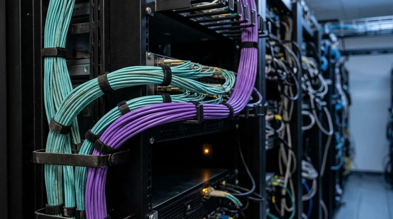
A 100G to 400G migration gets approved on a bandwidth slide and priced by a cabling contractor two weeks later. Those two numbers almost never match, and the gap is not the optics. It is the strand count.
Four 100G ports become one 400G port. Per port, the wrong PMD doubles what that port needs from the tray — 16 fibers instead of 8 — and asks for a connector family the hall does not have. On the right one, the eight fibers already terminated in the panel are the whole channel at four times the bandwidth. No datasheet tells you which case you are in; the answer depends on the plant you inherited.
The expensive failure in this work is not a slow link. It is a trunk that has to be pulled after the optics are already on site and the maintenance window is already booked.
Inventory the 100G fabric before you price a single optic
Most 100G fabrics are being replaced for one reason: an AI or GPU cluster needs more east–west bandwidth between a fixed number of racks than the leaf-spine fabric was built to carry. Two things follow from that. The run you are migrating is usually the one between leaf and spine, not the one to the servers. And the budget was approved for a port count, not a fiber count — which is why the first deliverable is an inventory, not a purchase order.
An inventory that counts ports will undercount fibers. Build it per path instead: for every rack-to-rack run that will carry a 400G port, record the switch and line card, the port mode, the installed optic, the fiber grade, the connector family and polish, the polarity method, the panel positions at both ends, and the spare strands.
The port mode is the field that gets skipped, and it is the one that changes the arithmetic. A port described as "100G" in a port-count spreadsheet is usually one of three different things: a native 100G port, a 100G port broken out to 4 × 25G toward servers, or a 400G port already broken out to 4 × 100G. Mix them and the strand total can be off by a factor of four, in either direction.
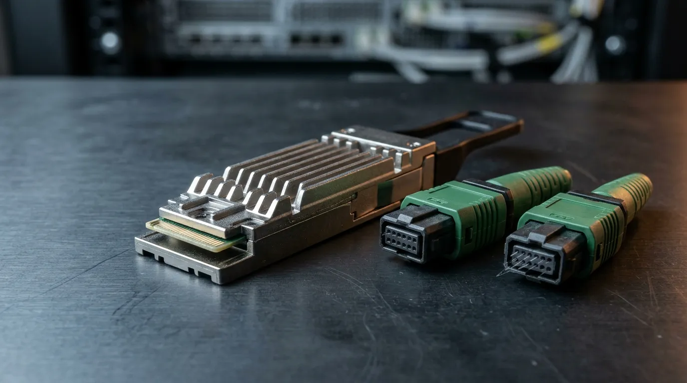
Two fields decide the arithmetic before any optic is chosen. The first is line-card port density: a 32-port QSFP-DD card and a 36-port OSFP card put different port counts in the same rack unit, and the housing is a thermal and density choice, not a fiber one — either housing is offered with the same PMD and the same front-panel connector. What matters is how many 400G ports one card presents, since that number times fibers per port is the run's strand demand. The second is module power and its thermal bill. Cisco's 400G QSFP-DD data sheet lists 12 W maximum for those parts, several times what the 100G QSFP28 it replaces draws, so 32 ports is 384 W of optics alone that were not in the rack's power or cooling budget. Check the per-rack headroom before you agree to a port count per rack.
The last three fields are the ones nobody remembers a year later — fiber grade, polish on each MPO end, polarity method — and they are recoverable now with a scope and a label, not from a spreadsheet.
Strand count, not port speed, decides a 100G to 400G migration
The 100G plant most sites are running is 100GBASE-SR4: four lanes, eight fibers, an MPO-12 connector, 100 m over OM4. Against that baseline the 400G PMDs split by what they demand of the plant, not by what they cost per port.
400G PMD | Fibers per port | Connector the port needs | What the existing plant has to already be |
|---|---|---|---|
400GBASE-SR4.2 | 8 | MPO-12 UPC | An OM4 100G-SR4 run; optics plus a polarity check |
400GBASE-SR8 | 16 | MPO-16 APC | A base-16 plant, or a new trunk |
400GBASE-DR4 | 8 | MPO-12 APC | OS2 with APC ends; UPC ends have to go |
400GBASE-FR4 | 2 | LC duplex | Duplex OS2 with capacity to spare |
Run the arithmetic on one leaf with 32 downlinks. Same 32 port positions, four times the bandwidth, and the fiber bill doubles or stays flat depending on one PMD decision: SR8 puts 512 fibers on that leaf, SR4.2 puts 256 — the count the 100G design already had. The derivation, including the duplex case, is in our 400G fiber cabling guide, and it is the reason this decision is made once, at the start, with the inventory in hand.
One thing belongs in the same decision because it outlives the optic: glass is replaced when a building is refurbished, not when a module generation turns over. A 16-fiber trunk pulled for SR8 is the footprint an 800G port will want later, which is the only argument for new glass in a 400G migration that has nothing to do with 400G.

One rack's worth of trunk. The port count on the spreadsheet says four ports; the tray says 32 fibers.
The reuse matrix: what the existing plant can carry
Reuse is a per-run decision, not a site-wide one. The newest cable in the hall is not always the one on the critical path.
Existing 100G plant | 400G PMD it can carry | What has to change | Verdict |
|---|---|---|---|
MPO-12, 8 fibers, OM4 (100G-SR4 trunks) | 400GBASE-SR4.2 (MPO-12 UPC, 100 m OM4) | Optics plus polarity/harness check; no glass change | Reuse the glass |
MPO-12, 8 fibers, OM4 | 400GBASE-SR8 | 16 fibers, MPO-16, APC polish | New trunk or overlay |
MPO-12, 8 fibers, OS2 | 400GBASE-DR4 (MPO-12 APC) | Polish verification; UPC ends must go | Re-terminate or replace |
MPO-24 OM4 trunk | Two or three 400GBASE-SR4.2 ports via a break-out panel | Panel and cassette work, not glass | Reuse with panel change |
Duplex OS2 LC pairs | 400GBASE-FR4 (one pair), or 4 × 100G-FR1 (four pairs) | Nothing in the glass; module and reach check | Reuse unchanged |
MPO-16 trunks from an earlier 800G pilot | 400GBASE-SR8 natively | Nothing | Reuse, and prefer this path |
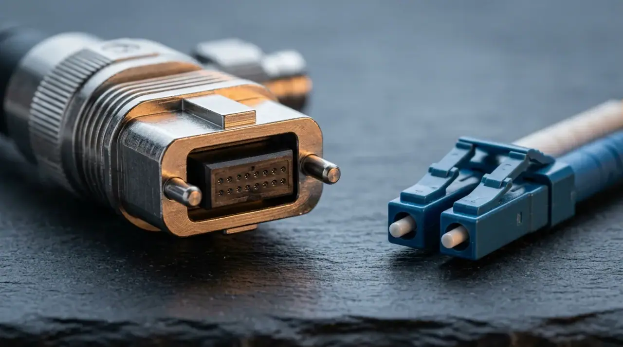
The matrix turns on polish, and polish is set by the module rather than the glass: SR4.2 is the one multimode 400G part specified at MPO-12 UPC, and every other row wants APC ends — so a run that tested clean at 100G can fail at the first 400G acceptance test without a single fiber being touched. It turns on connector base too, since base-8 and base-16 do not mate: a run crossing that line crosses it at a panel with one connector family on each face, a line item on the plan rather than a discovery on the night. The position maps are in our MPO-12 vs MPO-16 vs MPO-24 comparison, and the duplex alternative, including MDC and SN, in the MPO vs LC high-density cabling piece.
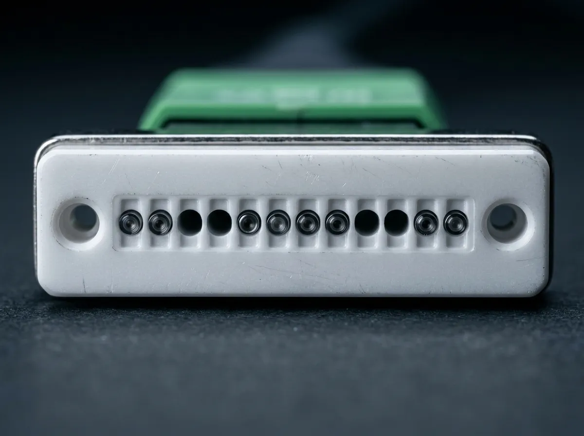
Twelve positions, eight carrying fiber and four dark. The dark four cannot be re-sold as a second channel; the margin is the eight that are already terminated — which is why SR4.2 lands on this plant unchanged.
Re-pinning and polarity: what changes when the far end changes
Here is where a plan that looks cheap goes wrong. The trunk survives; the mapping through it does not.
Polarity is the transmit-to-receive mapping across the whole channel, and all three methods — A, B and C — are legitimate; the mapping tables are in our MPO polarity Type A/B/C guide. What changes in a migration is not the method but the assembly at the far end. A trunk that was polarity-correct at 100G is not automatically polarity-correct at 400G, because the harness or cassette it now lands on was built for a different mapping and carries its own. On the reuse path the glass is the same glass and the optics are new, which means the polarity evidence you hold is evidence about a channel that no longer exists.
The physical half is harder to fix. Guide pins sit on one side of every MPO mating and holes on the other, and the pins belong to the assembly, not the port. Re-pinning an installed plant means taking every affected end out of service, changing which side carries the pins, and re-testing it — on the bench, in daylight, before the window, never inside it. A re-pinned end also has no acceptance history: the loss figure you inherited was measured across a different connector geometry, so the old test data cannot be carried forward into the new channel.
The failure this prevents is quiet. A mismatched mapping passes an insertion-loss test, because loss is what that test measures, and the link arrives at the far-end transmitter instead of its receiver. Nothing in the acceptance report flags it. What catches it is a polarity check by measurement on every channel in the wave, before traffic moves.
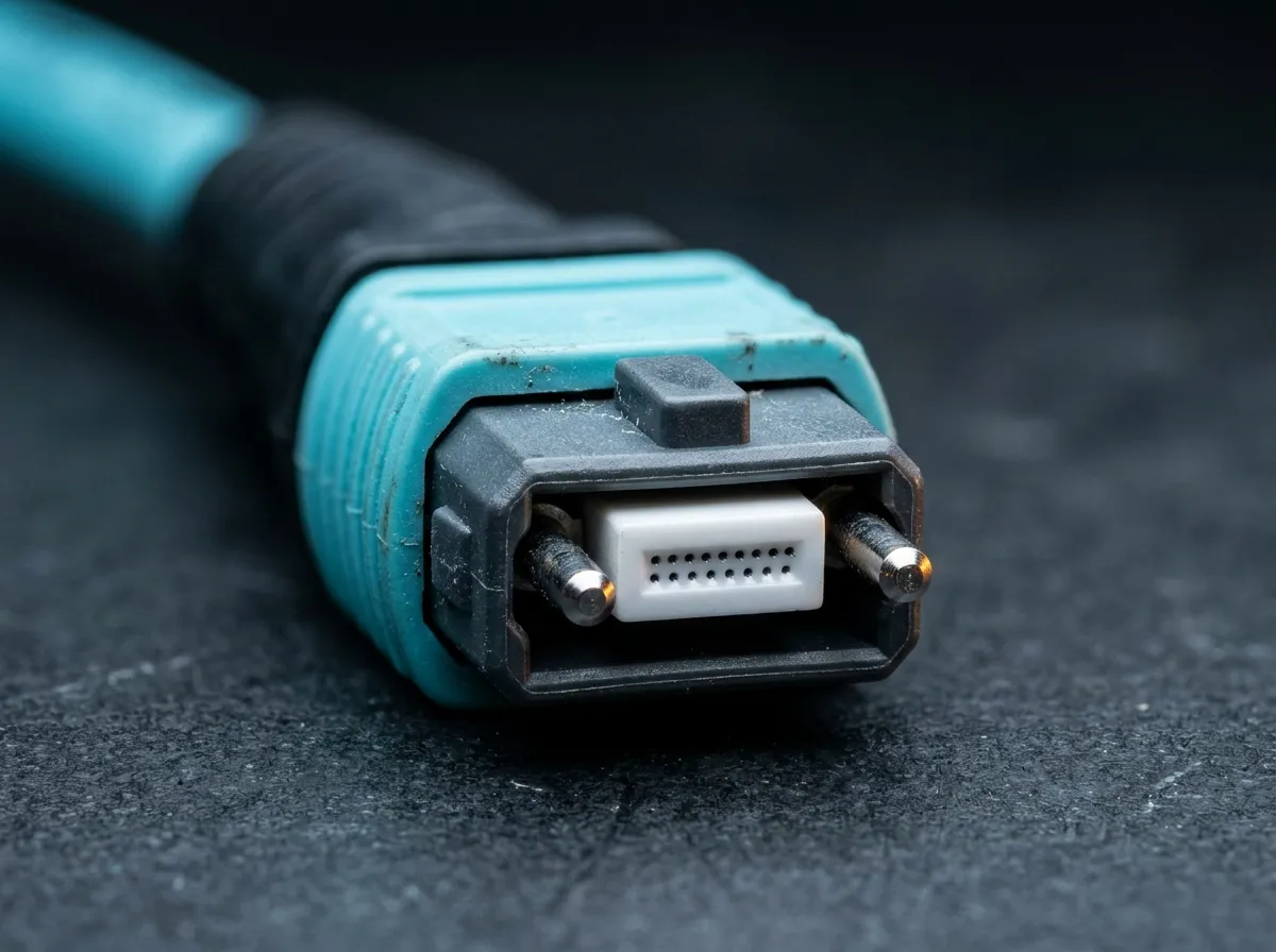
Guide pins on one side, holes on the other. Re-pinning an installed end flips which side carries them — and the end you get back has no test history you can inherit.
Where the channel budget narrows: the cassette you add
The 400G ceiling is not the problem. 400GBASE-SR8 allows 1.9 dB of channel insertion loss at 100 m over OM4 (IEEE 802.3cm-2020, Clause 138), and 400GBASE-DR4 allows 3.0 dB over 500 m (IEEE 802.3bs-2017, Clause 124, tabulated for 400GBASE-DR4 by TIA). A 100GBASE-SR4 channel at 100 m is held to the same 1.9 dB. What narrows in a migration is not the ceiling but the speed you spend it at, because the plant stops mating directly.
A channel built on reused glass has the four mated pairs it already had, so the channel itself does not get worse. The conversion does. One cassette taking a 12-fiber trunk onto a 16-fiber port adds two mated pairs — 0.7 dB at the usual 0.35 dB planning value for a low-loss MPO mating — to a channel that already sits at 1.75 dB against the 1.9 dB ceiling. That 0.15 dB of margin does not survive 0.7 dB of new matings: the channel lands 0.55 dB over the ceiling. That is the arithmetic that exists only in a migration: the span was never what spent the budget, and every mating you add spends it.
Which is also why "it came up" is not an acceptance result. 400G runs four-level PAM4 on each lane, at about 9–10 dB less signal-to-noise headroom than an NRZ lane at the same symbol rate, and forward error correction on the host is what absorbs the difference. A channel with no margin left still trains and still passes traffic. Test against the 1.9 dB ceiling, not against link state.
Cut over in waves, with a rollback you have rehearsed
The cutover is where a good plan meets a bad night. Three rules keep it contained.
Wave zero gets a rack pair, not a site. Pick the lowest-risk pair that still represents the target fiber, connector, PMD and traffic profile. Run it for two weeks: errors, DOM values, temperature, and the actual time the window took against the time you estimated. That last number is the one that sets the rest of the schedule.
Pre-stage everything that can be pre-staged. New optics coded and labelled by position, config templates applied but shut, out-of-band access verified on both ends, and the old 100G optics left in a labelled bin in the same rack. Rollback then comes down to three things that are already in place — the old modules by position, the saved config, and spare patch leads in the rack — which is a re-plug and a restore rather than a search for parts. Time it during wave zero. A rollback you have never executed is a hope, not a control.
Do not re-pin a trunk inside a maintenance window. Re-pinning, re-terminating and harness swaps happen on the bench in daylight, tested before the window opens. The window is for inspecting, mating, testing and enabling — and it is measured in ends, not ports. A trunk end takes a technician roughly 20 to 30 minutes to inspect to IEC 61300-3-35 and test per fiber, so a wave of 48 trunks is 96 end procedures — roughly 40 technician-hours, a week for one technician or a day for a five-person crew — before any traffic moves. That line item, not the module price list, is what decides whether the reuse path was worth taking.
The bridge that makes waves affordable is breakout. A DR4 port runs as 4 × 100G into QSFP28 100G-DR, FR or LR modules while the leaf stays at 100G, and the SR4.2 part breaks out to four 100G-SR1.2 links on the multimode side. Choose a PMD that cannot break out and you have quietly removed the option to move the spine first.

The window is spent here: inspect, mate, test, enable. Every trunk consumes two of these before traffic moves.
Test, keep, or replace: the gate before the next wave
Wave zero does not only set the schedule; it sets the evidence standard every later wave has to meet.
Four records come out of a completed wave, and a wave that cannot produce them cannot be rolled back with confidence. End-face inspection results for every MPO position, to the IEC 61300-3-35 criteria, before mating. Per-fiber insertion loss against the PMD's ceiling rather than per-connector loss, because a per-connector number averages a bad position away: a cassette can test clean at the connector and still drop a lane. A polarity measurement per channel, taken at the far end rather than read off a label. And the whole set filed against the channel, equipment cords included, since that is the baseline an eighteen-month degradation gets compared to.
Then split the bill into two lists. Keep: the glass in any run whose fiber count, grade and polish already match the target PMD; duplex single-mode paths; panels whose connector base matches; spare strands, which stop being waste and become migration reserve. Replace: the connector family when the base changes, harnesses built for the old polarity, cassettes that cannot host the new ferrule, and any trunk whose end faces were already at the edge of the acceptance criteria.
The cost of a migration is driven by ends, truck rolls, downtime windows and rework — not by the module price list. A crew that has to return for one bad cassette costs more than the cassette, the trunk and the optics combined. That is the argument for the extra day on inventory and bench work before the first window.
When the matrix says replace rather than re-terminate, the assemblies are the one part of the plan worth specifying rather than shopping for: fiber count, connector and polish per end, polarity method and pin gender stated per position, factory-terminated and tested, with per-fiber loss data shipped alongside the goods. TTI Fiber builds those to that sheet — 8–72 fiber harnesses, 12–72 fiber trunks and 12- or 24-port cassettes, polarity and pin gender per end — MPO/MTP trunk and harness assemblies.
Our data center fiber cabling hub collects the rest of the reference material — media choice, connector counts, polarity and the loss arithmetic behind these numbers. If your rack-and-panel layout changes with the optics, the patch panel selection guide covers the density and access trade-offs that decide how the next cutover runs.