Vibration Damper Spacing on ADSS Cable: How Many, and Where?
Vibration Damper Spacing on ADSS Cable: How Many, and Where?
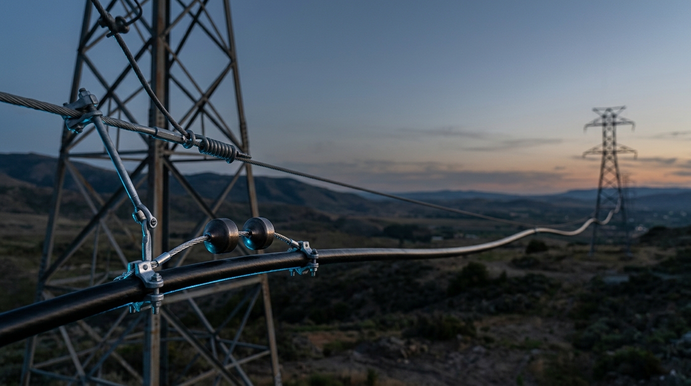
Search for vibration damper spacing and you will find a table. It will tell you that spans under 200 m need no dampers, that 400–700 m needs four, and that the first damper sits 0.77 m from the end of the armor rods. The table looks authoritative. It gets copied from vendor page to vendor page.
That table was almost certainly computed for an OPGW cable — a stranded aluminium-clad steel conductor with a completely different diameter, mass and tension from the ADSS cable on your reel. The numbers in it are not physical constants. They are the output of a formula, evaluated once, for someone else's cable, under an assumed wind speed nobody wrote down.
This article does the opposite. It shows you where the spacing number comes from, so you can produce the one that belongs to your span.
1. Why a span vibrates at all
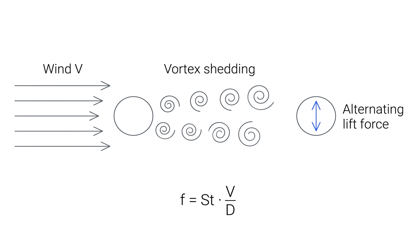
Point a steady, smooth wind at a cylinder and the flow cannot stay attached to the back of it. It separates, and it separates alternately — one vortex peels off the top, then one off the bottom, then the top again. This is vortex shedding, and the alternating pressure it leaves behind pushes the cylinder up, then down, then up.
Do that at the natural frequency of a tensioned cable and you get a standing wave along the whole span. That is aeolian vibration: high frequency, low amplitude — millimetres to centimetres, and 3 to 150 Hz.
The shedding frequency is set by one clean relationship:
f = St · V / D >f = shedding frequency (Hz) · V = wind speed (m/s) · D = cable outer diameter (m) · St = Strouhal number
The Strouhal number is the useful part. For a circular cylinder it is remarkably stubborn: "Over four orders of magnitude in Reynolds number, from 10² to 10⁵, the value of the Strouhal number remains close to 0.2." Every wind speed and cable diameter you will ever string sits inside that range. So St ≈ 0.2, and the frequency your cable sees is essentially 0.2 · V / D.
Aeolian vibration needs laminar wind to sustain itself — roughly 1 to 7 m/s. Below that there is not enough energy; above it the wind becomes turbulent and the shedding loses coherence. A gale does not cause aeolian vibration. A quiet, steady breeze across an open river crossing does, all night, for twenty years.
2. The cable does not break in the middle
An amplitude of a few millimetres sounds harmless, and along most of the span it is. The cable is free to move, so it moves, and nothing is stressed.
At the suspension clamp it is not free to move. The cable is rigidly gripped on one side of the clamp mouth and vibrating on the other, so all of the bending concentrates into a few centimetres of cable right at the clamp lip. Multiply a few millimetres of deflection by 50 Hz by twenty years and you have around 30 billion bending cycles at a single point.
That is why aeolian vibration is described as "the principal cause of failure of conductor strands." On a metallic conductor the strands fatigue and fracture. On an ADSS cable the failure is quieter and, for a network operator, worse: the jacket abrades and cracks at the clamp, the aramid strength members fret, and long before anything falls down, the fibre inside starts accumulating attenuation from microbending. You do not see it on an inspection walk. You see it on an OTDR trace, as a span that has been slowly getting worse for three years.
Dampers exist to absorb that energy before it reaches the clamp.
3. The number that decides your damper count is not span length
Every table on the internet indexes damper count by span length. Span length is a proxy, and a poor one.
What actually determines whether a span will vibrate destructively is how hard it is strung relative to how heavy it is — the H/w ratio: horizontal tension H divided by weight per unit length w. It has units of length, and it is the single parameter the industry uses to set a safe design tension. CIGRÉ's Technical Brochure 273, Overhead conductor safe design tension with respect to Aeolian vibrations, is built around exactly this question.
Why H/w and not span? Because tension is what stores the energy. A cable strung tight has a high wave speed, vibrates readily, and dissipates very little internally. A cable strung slack sags, moves as a floppy catenary, and eats its own vibration energy. Two 500 m spans, same cable, one at 15% of rated tensile strength and one at 30%, are not the same engineering problem — but a span-length table gives them the same answer.
ADSS deserves particular care here. It is light. Wave speed goes as √(T/m), so for a given tension a low mass per unit length means a high wave speed, long loops, and a high H/w for what feels like a modest stringing tension. Its jacket is also smooth and perfectly circular, which makes it an unusually cooperative vortex shedder — a stranded conductor's surface roughness disrupts the shedding slightly; an extruded polyethylene jacket does not.
How much self-damping your specific cable has is a measured property, not something to infer from the fact that it is made of plastic. Ask for it. IEEE 1222, the ADSS standard, covers installation guidelines and accessories precisely because the cable and its hardware have to be qualified together.
The practical version: span length tells you roughly how many dampers. Tension tells you whether you have a vibration problem at all. If your everyday tension is being pushed up to flatten sag and win a clearance argument, you have just made the damping problem harder, and no table will tell you that.
4. Where the spacing number actually comes from
Here is the chain, end to end.
A tensioned cable carries transverse waves at speed c = √(T/m), where T is tension (N) and m is mass per unit length (kg/m). The wind drives it at f = St · V / D. A standing wave forms, and its wavelength is:
λ = c / f = D · √(T/m) / (St · V)
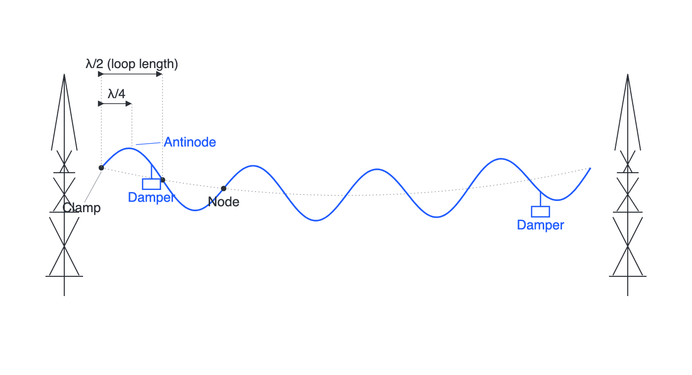
The standing wave has nodes (zero motion) and antinodes (maximum motion). Nodes recur every half wavelength; antinodes do too, offset by a quarter wavelength, so each antinode sits exactly halfway between two nodes. The clamp is forced to be a node. Therefore the first antinode is at λ/4, and the next node is at λ/2. That node-to-node distance is what the trade calls the loop length.
Now, where does the damper go?
The intuitive answer — and the one you will read on Wikipedia, that "dampers are typically installed at the nearest anti-nodes" — is λ/4. That is right for a single frequency, and a real span does not have a single frequency. It is being driven anywhere from 3 to 150 Hz, all at once, and each of those frequencies has its own wavelength and its own nodes. A position that is an antinode for one is a node for another, and a damper sitting on a node is a paperweight.
So the real rule is defensive rather than optimal. Compute the loop length at the highest frequency you expect, and place the damper just inside it. Every lower frequency has a longer wavelength, so the damper is then strictly inside the first loop for every mode in the band — never at a node for any of them. That is why schedules specify a distance a little short of λ/2 rather than exactly λ/4 or exactly λ/2.
Which brings us back to L1 = 0.415 · D · √(T′/M).
Set the placement distance to the loop length, λ/2 = D · √(T/m) / (2 · St · V), and compare. They are the same formula. The mysterious 0.415 is just 1 / (2 · St · V). Put in the Strouhal number for a cylinder, St = 0.2, and solve for the wind speed the constant implies:
1 / (2 × 0.2 × V) = 0.415 → V ≈ 6.0 m/sSo the constant is not a constant. It is somebody's design wind speed, baked in and then forgotten — a decision that a 6 m/s sustained wind is the fastest this line will see often enough to matter. That is a reasonable call for many lines. It is not a law of nature, and it is not necessarily true of yours.
(The arithmetic here is exact; reading it as a 6 m/s design wind is our reconstruction, not a published derivation.)
Put your own cable in it
Here is why this matters more for ADSS than for the steel-and-aluminium cable the constant was probably calibrated on.
Take a 24-fibre ADSS cable, D = 14 mm, m = 0.16 kg/m, strung at an everyday tension of T = 8 kN. (Illustrative numbers — use your own datasheet.)
√(T/m)= √(8000 / 0.16) = 223.6 m/sλ/2= 0.415 × 0.014 × 223.6 = 1.30 m
Now run the same formula for a typical OPGW: D = 10.5 mm, m = 0.384 kg/m, T = 12 kN.
√(T/m)= √(12000 / 0.384) = 176.8 m/sλ/2= 0.415 × 0.0105 × 176.8 = 0.77 m
There it is. 0.77 m for the OPGW; 1.30 m for the ADSS — nearly double. ADSS is light, so for a comparable tension its wave speed is much higher, its wavelengths are much longer, and its dampers belong much farther out from the clamp. Install the ADSS damper at the OPGW's 0.77 m and you have placed it at roughly 0.6 of a loop length — inside the first loop, so not catastrophic, but well away from where it was designed to sit, and eating damper efficiency for no reason.
That 0.77 m is the number in the table you found. It was never yours.
Two practical notes. Vendors place the damper a defined distance inside the loop length — commonly a few centimetres, sometimes expressed as 0.7–0.9 × λ/2 — because V is a band, not a number. And on long spans the second and third dampers are positioned to cover the rest of the band; a tuned damper is narrow, and a span driven from 1 to 7 m/s is worked across a wide spread of wavelengths.
5. So how many dampers per span?
The honest answer is that the count falls out of the tension and the exposure, not the span. But engineers need a starting point for a bill of materials, and this is the shape of the consensus:
Span | Typical damper count | What is really going on |
|---|---|---|
Under ~200 m | Often none | Short loops, low stored energy; the cable's own damping usually wins |
~200–400 m | 2 (one per end) | The standard case: "normally two dampers per span" |
~400–700 m | 4 (two per end) | One damper cannot cover the frequency band on a long, energetic span |
Over ~700 m | 6+, and a vibration study | River and valley crossings; treat as bespoke engineering |
Read that table the way it deserves to be read. It is a sanity check on a number you calculated, not a substitute for calculating it. Every threshold in it moves if your tension moves. A tightly strung 350 m span across open water can need more damping than a slack 500 m span in a forest.
Three things push you toward "more than the table says": high H/w, terrain with long uninterrupted laminar wind fetch (water, ice, flat farmland, deep valleys aligned with the prevailing wind), and long design life. If TTI Fiber's ADSS is specified out toward its 880 m span capability, you are in bespoke territory by definition — that span gets a vibration analysis, not a lookup.
6. Spiral or Stockbridge-type?
Two families of hardware, two different mechanisms.
A Stockbridge-type damper — the "dogbone" — is a tuned mass damper: two masses on a short flexible messenger, clamped at its middle to the cable. It has its own resonant frequencies, and near them the messenger flexes and dissipates energy as internal friction. Tuned correctly it is very effective. Placed at a node, or tuned to the wrong band, it is a paperweight.
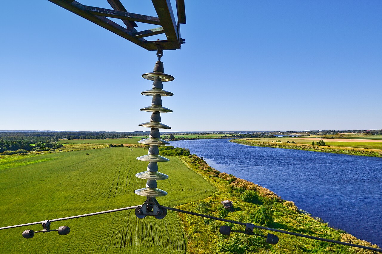
Photo by alinco_fan via Wikimedia Commons, CC BY 3.0
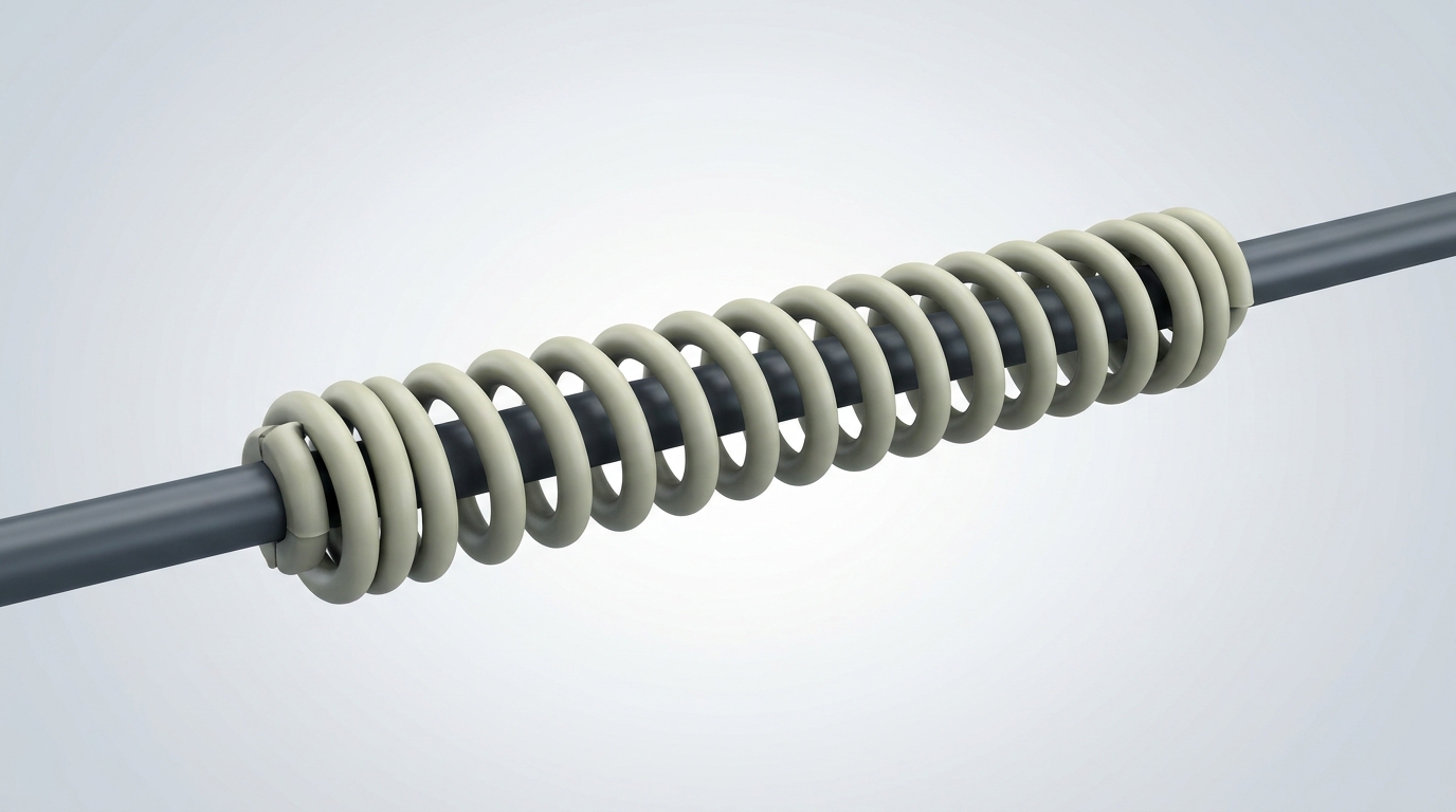
A spiral vibration damper (SVD) is a stiff helix of PVC or polyethylene wrapped around the cable over a metre or two. It works by mass and by impedance mismatch: it detunes the cable locally and rubs against it, spreading damping over a length rather than concentrating it at a point.
The trade is straightforward:
Spiral (SVD) | Stockbridge-type | |
|---|---|---|
Placement sensitivity | Low — forgiving of position | High — must be at the antinode |
Frequency coverage | Broad, shallow | Narrow, deep |
Best for | Short-to-medium spans, moderate tension, small-diameter cable | Long spans, high tension, high stored energy |
Installation | Hand-wrapped, no tools | Bolted clamp, torque-controlled |
One vendor markets its spiral product on the promise that there is no need to calculate positioning. That is a real advantage — and also an accurate description of the limit. Position tolerance is what you buy instead of depth of damping. On a 250 m distribution-line span it is the right trade. On a 700 m crossing at 25% RTS it is not, and the calculation you were trying to avoid is exactly the one that would have told you so.
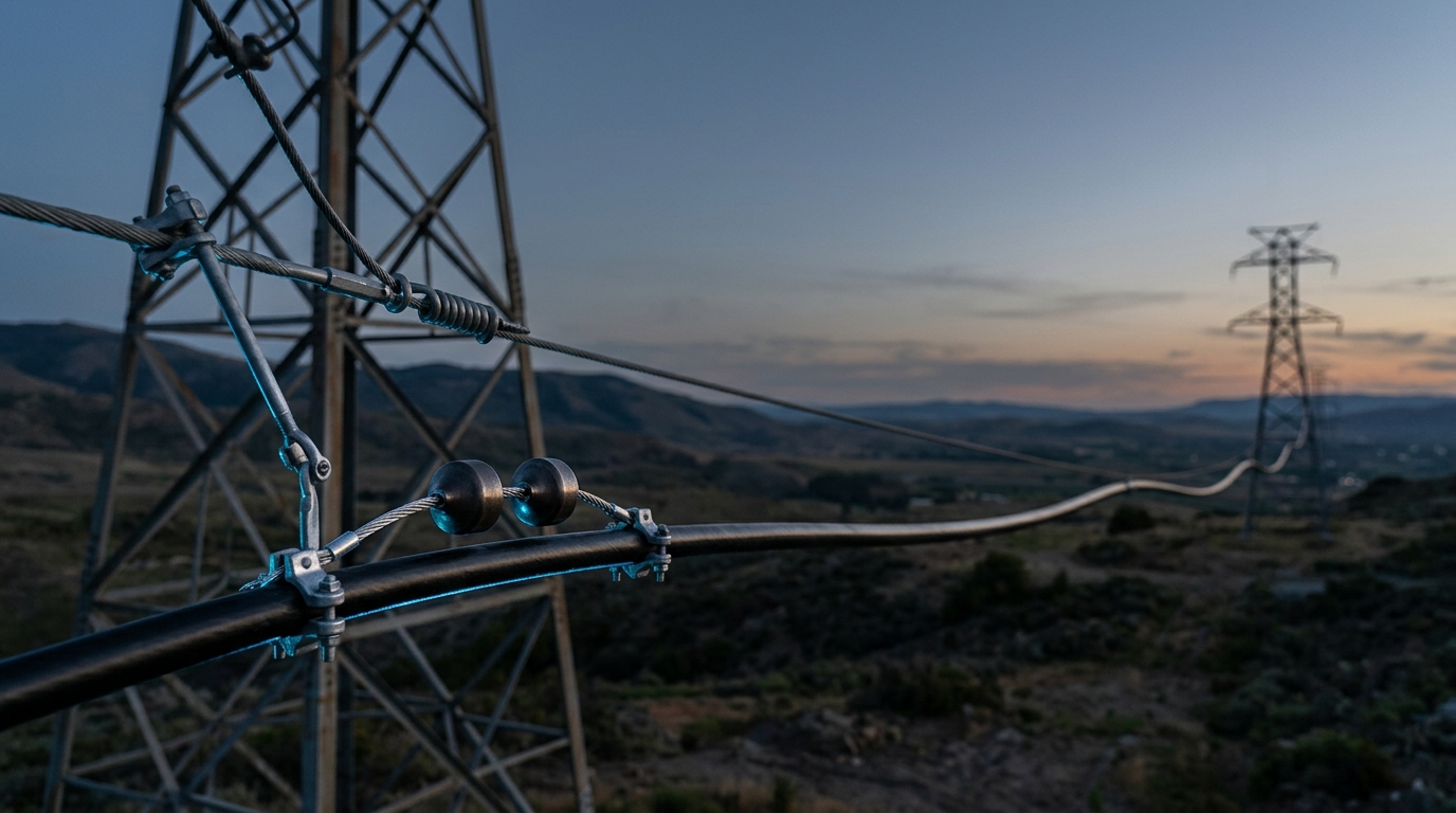
Both are installed over armor rods, which distribute the clamp's grip and give the damper a defined datum to be measured from. When a schedule says "0.77 m," it means 0.77 m from the end of the armor rod, not from the clamp bolt. Getting that reference point wrong is a common and expensive way to install a damper at a node.
7. What to do on your line
- Get D, m and RTS from the cable datasheet. Not from a similar cable. Diameter drives frequency; mass drives wave speed. Both are in the formula.
- Establish the everyday tension, and express it as H/w and as a percentage of RTS. Remember that tension is not a fixed number — it climbs in the cold. Our note on how temperature changes affect fibre performance covers why the tension you strung at is not the tension you will vibrate at in January.
- Characterise the exposure. What is the prevailing wind, and does it arrive laminar? A 400 m span over a lake is a different animal from a 400 m span through trees.
- Compute λ/2 at the top of your design wind band, and place the first damper just inside it, measured from the end of the armor rods — not from the clamp bolt.
- Sanity-check against the table in §5. If the calculation and the table disagree by more than one damper, find out which of your assumptions is wrong before you order hardware.
- On long, high-tension or high-value spans, ask for a vibration analysis. Any competent ADSS manufacturer will run one against your span, tension and terrain. This is a normal request, not an exotic one.
If the line runs on a power corridor, the cable choice sits upstream of all of this. All-dielectric construction is what makes the cable safe to hang in an energised field in the first place — the same reasoning behind non-metallic aerial designs like GYFTY. And if you are still deciding between hanging a dielectric cable and putting the fibre in the earth wire, the comparison between OPGW and traditional overhead wires is the place to start — the aeolian physics above applies to both, but the damper schedules genuinely do not transfer between them.
The one thing to take away
0.415 is not a constant. It is a wind speed in disguise.
Spacing follows from loop length; loop length follows from your cable's diameter, mass and tension; and the count follows from how hard you strung it, not how far apart the towers are. A span-length table is a fine way to check your answer and a terrible way to get it.
TTI Fiber manufactures ADSS cable in-house — 2 to 576 fibres, PE and AT jackets, spans to 880 m, tested to IEEE 1222 and IEC 60794-1-1. We make cable, not damping hardware, so we have no stake in which damper you hang on it. What we can do is give you the D, m, RTS and self-damping data your calculation needs, and run a vibration analysis against your actual spans and terrain before you commit to a bill of materials.
Send us your span schedule and wind exposure and we will come back with the tension design and the damper positions. More outside-plant engineering guides are collected in our Outside Plant & Backbone section.