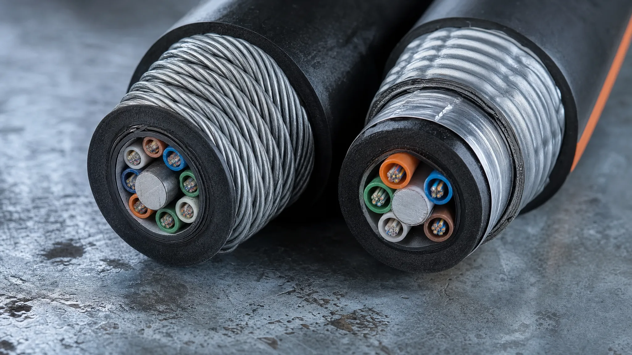
ADSS Tracking Resistance: A Field Guide
ADSS Tracking Resistance: Space Potential, AT Jackets, and the Standards That Actually Apply
A jacket compound that passed a 4.5 kV inclined-plane tracking test can still burn through in a few years. Not because the compound was oversold, but because the cable was hung in the wrong place on the tower.
That is the part most ADSS jacket discussions skip. Tracking resistance gets treated as a checkbox — you either bought the "anti-tracking" cable or you didn't. In the field it behaves like a margin: a property of the jacket material set against an electrical stress that your route, your tower geometry, and your attachment point determine long before the cable is manufactured.
Three numbers dominate every ADSS jacket conversation: 12 kV, 25 kV, and 4.5 kV. Exactly one of them comes from a standard, and it is not the one most datasheets imply. This guide walks the failure mechanism, shows what space potential actually is and how to use it to your advantage, sorts the standards that apply from the three that get miscited constantly, and ends with specification language you can paste into a tender.
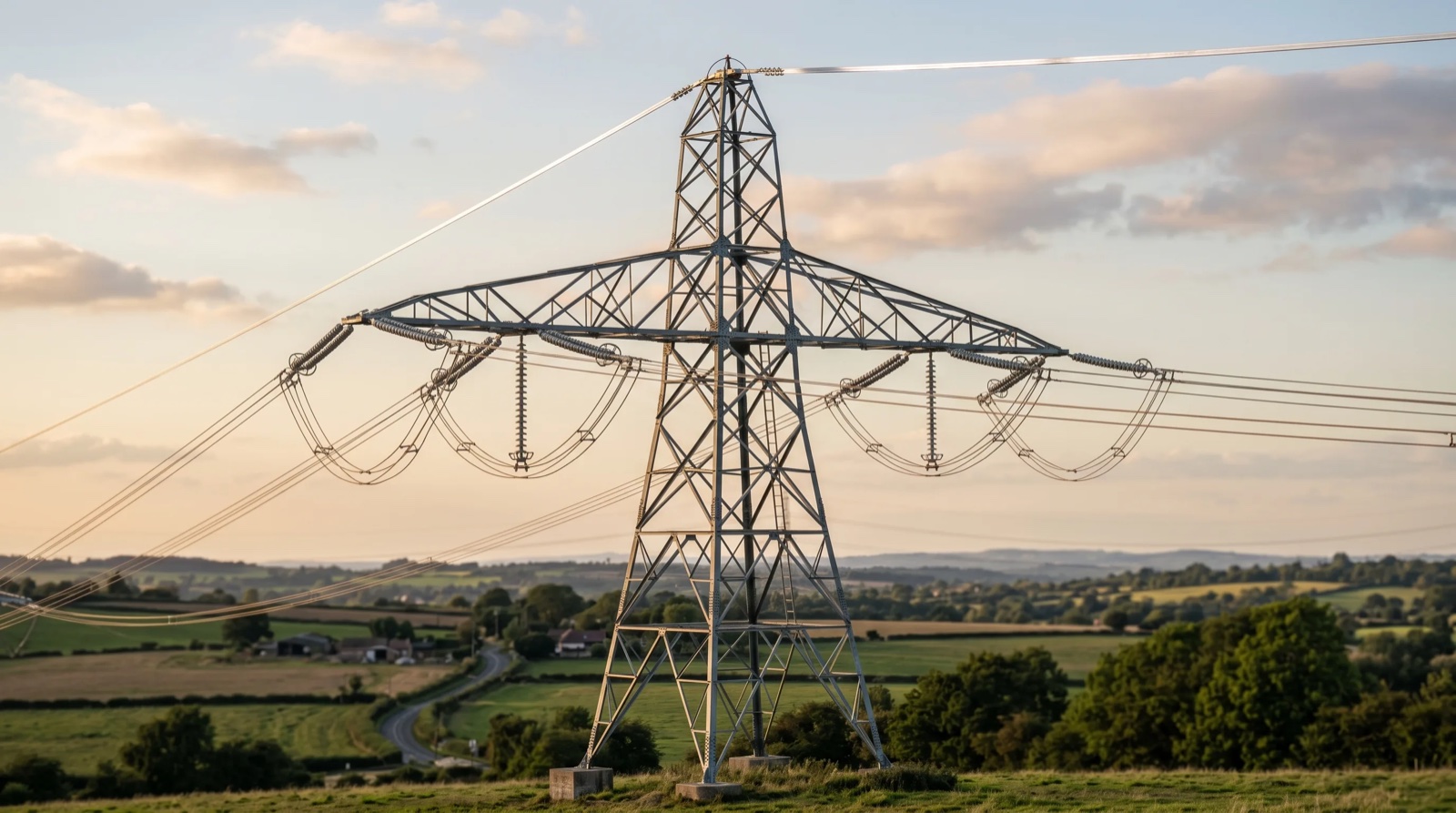
What actually destroys an ADSS jacket
An ADSS cable contains no metal. That is the whole point of it — no OPGW-style metallic path to bond, no shutdown required for stringing, no induced-current path to manage. But it is also the source of the problem: with no conductive core to hold it at ground potential, the cable floats electrically. It sits in the field between energised conductors and earth, and it takes on whatever potential that field imposes at its position.
A small current flows across the jacket surface toward the grounded hardware at either end. On a clean, dry jacket this current is negligible. Then the weather changes.
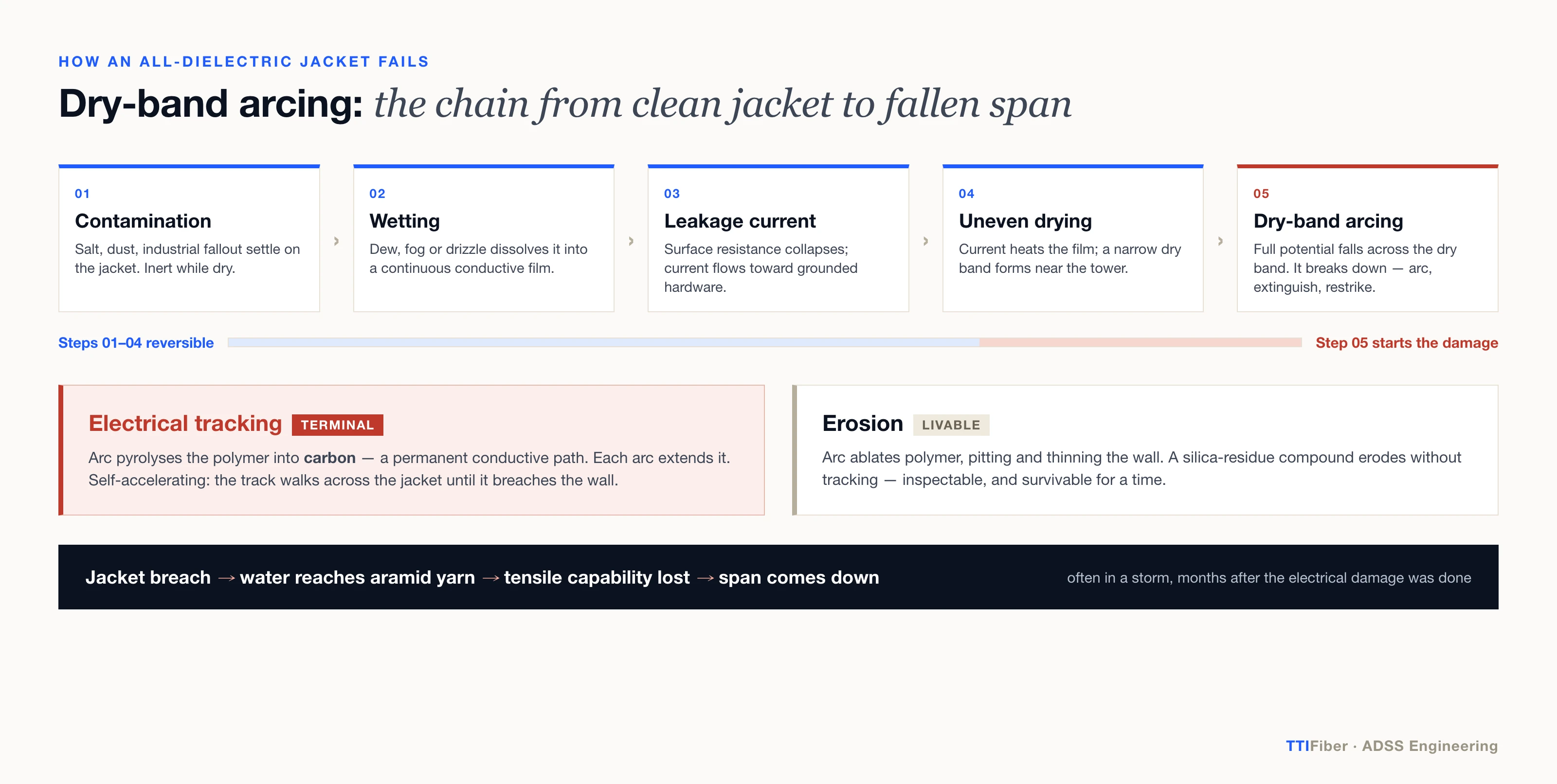
The chain runs like this:
- Contamination lands. Salt, cement dust, agricultural aerosol, industrial fallout, bird droppings. On its own, inert.
- Wetting. Dew, fog, drizzle, condensation. The contaminant dissolves and the jacket surface carries a continuous conductive film.
- Leakage current rises. The film shorts the surface resistance down by orders of magnitude. Current now flows in earnest along the cable toward ground.
- Drying is uneven. That current heats the film. It evaporates fastest where current density is highest — typically near the hardware at the tower. A narrow dry ring forms across an otherwise wet, conducting surface.
- Dry-band arcing. The full potential difference that was distributed across the whole wet surface now falls across that few-millimetre dry band. It breaks down. An arc strikes, scours across the band, extinguishes, restrikes — hundreds of times per hour in the right conditions.
Everything up to step 5 is reversible. Step 5 is where the jacket starts dying, and it dies in one of two ways.
Erosion is mechanical-thermal: the arc ablates polymer, pitting the surface and thinning the wall. Electrical tracking is worse. The arc pyrolyses the polymer, and if the compound's chemistry allows it, the residue left behind is carbon. Carbon conducts. Each arc extends a permanent conductive filament across the jacket surface, and the next arc starts from the tip of that filament. Once carbon tracking initiates, the process is self-accelerating and terminal — the track walks across the jacket until it breaches the wall.
What it breaches into is the reason this matters. Under the jacket sits the aramid yarn that carries the entire mechanical load of the span. Water reaches it. It loses tensile capability. The span comes down — often in a storm, months after the electrical damage was actually done.
Two distinctions worth being precise about, because they get conflated:
- Corona is not tracking. Corona is ionisation of the air near a high-field surface — it degrades polymer slowly and it is a genuine concern at sharp hardware edges, but it is not the dry-band mechanism. Corona can seed tracking by roughening and oxidising the surface. It does not, by itself, carve carbon paths.
- Tracking is not erosion. A silicone-filled compound may erode substantially and never track, because its pyrolysis residue is silica, not carbon. Erosion you can inspect and live with for a while. Tracking you cannot.
Arizona State University's transmission line group did much of the foundational experimental work on this — Shi and Karady's 2004 characterisation of dry-band arcing on ADSS cables (IEEE Transactions on Power Delivery, 19(4):1936–1940, DOI 10.1109/TPWRD.2004.835391) remains the reference for the arc behaviour itself, and ASU's later work extended it into predictive modelling of dry-band arcing failure.
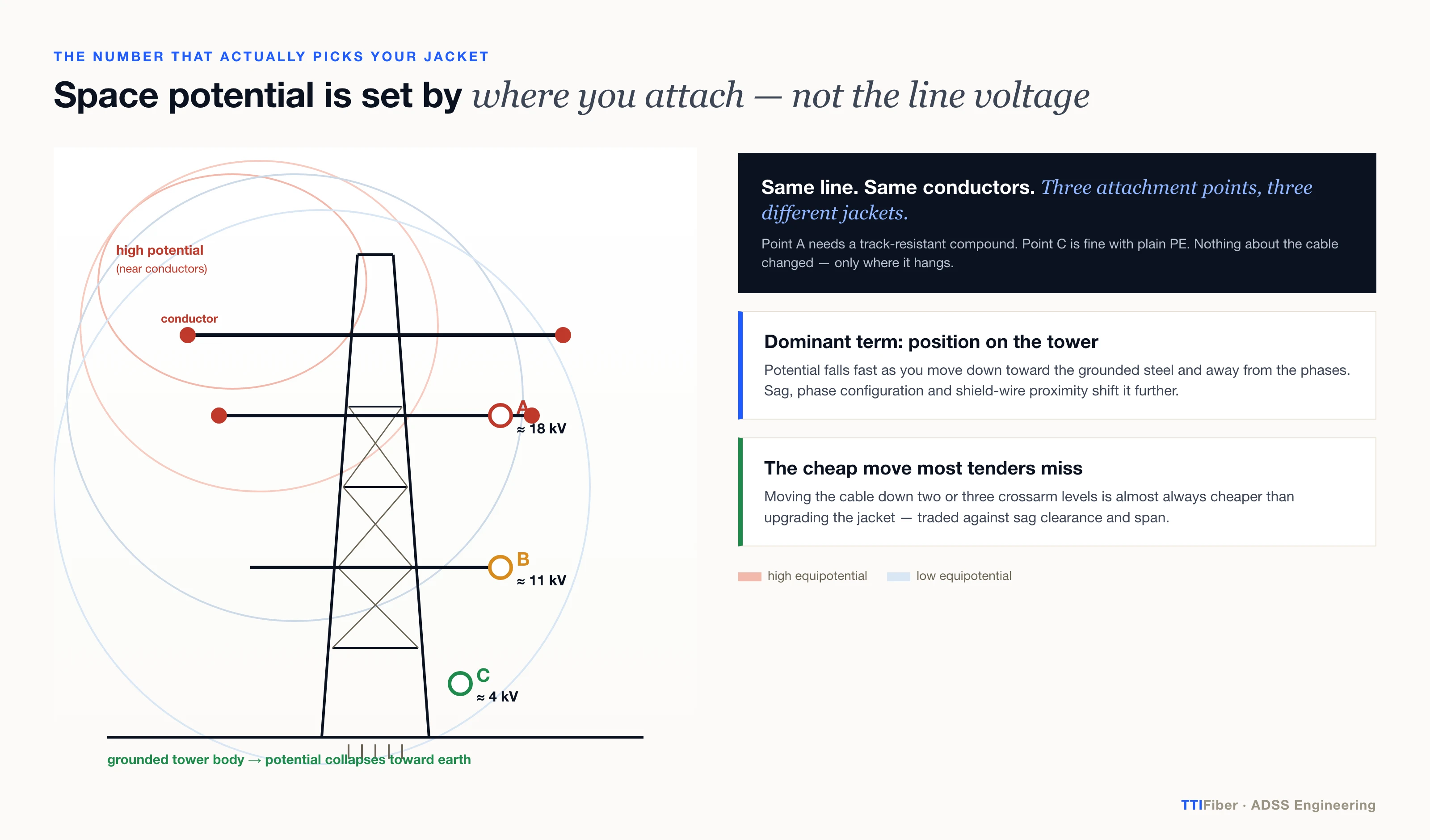
Space potential is the number that decides everything
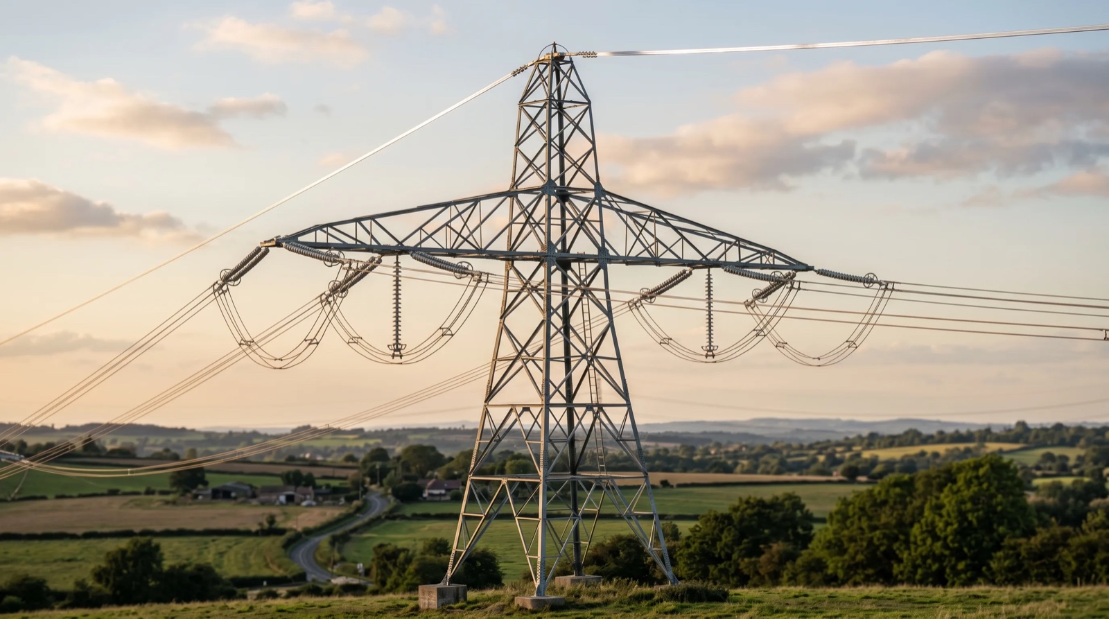
Ask what voltage an ADSS cable "sees" and the instinctive answer is the line voltage. That answer is wrong, and building a jacket decision on it is how utilities end up buying the wrong cable in both directions — over-specifying on a 400 kV line where the cable hangs low on the tower, under-specifying on a 132 kV line where it hangs between the phases.
The quantity that matters is space potential: the electrical potential that would exist at the point in space occupied by the cable, if the cable were not there. It is a property of the location, not of the line.
Space potential at a candidate attachment point is set by:
- Line voltage and phase configuration. Vertical, horizontal, delta, single- or double-circuit — each produces a different field map.
- The cable's position on the tower. This is the dominant term. Potential collapses as you move down the tower toward the grounded steel and away from the conductors.
- Sag. The cable is not at its attachment height at mid-span. It sags toward — or away from — the conductors, and mid-span geometry can present a materially different potential than the tower. This is one of several reasons ADSS sag and tension design is not separable from jacket selection.
- Proximity to the shield wire and to the tower body, both of which are at or near earth potential and pull the local field down.
Here is the practical consequence, and it is the single most useful thing on this page:
Moving the cable is almost always cheaper than upgrading the jacket.
A candidate position two or three crossarm levels lower can drop space potential from the high teens into low single digits — taking you from "you need a track-resistant compound" to "standard polyethylene is fine," on the same line, with the same conductors, on the same day. The trade is against sag clearance, span length, and mechanical loading, so it is a real engineering trade rather than free money. But it is a trade most procurement conversations never surface, because by the time the cable is being quoted, the attachment point has been fixed by someone who was not thinking about jacket chemistry.
You get the number one of two ways: electrostatic field simulation of the tower and conductor geometry (2D or 3D finite-element; any competent ADSS supplier or utility engineering group can run it), or direct field measurement with a potential probe on an existing structure. Ask for it as a deliverable, on the specific attachment points you are considering — not as a single number for "the line."
The three numbers everyone quotes — and where they actually come from
This is where the industry gets sloppy, and where a specification can be tightened for free.
The claim you'll see | Where it actually comes from | Is it normative? |
|---|---|---|
PE jacket is acceptable up to 12 kV space potential | Supplier application notes — e.g. Sterlite's ADSS application note states MDPE is used "up to 12 kV space potentials"; AFL publishes comparable guidance | No. Not a clause in any ADSS standard. |
Track-resistant (AT) jacket is required from 12 kV to 25 kV | Same supplier application notes | No. Industry convention, empirically grounded, not codified. |
An anti-tracking compound must withstand 4.5 kV | IEC 60587:2022, Method 1 (constant voltage). 4.5 kV is the level the industry treats as the track-resistant threshold — the standard also defines lower (2.5, 3.5 kV) and, for higher grades, 5.0 and 6.0 kV levels | Yes — but it is a material test, and 4.5 kV is a test level, not a service rating. |
The compound is "Class A anti-tracking" | Nowhere. No IEC or IEEE standard defines "Class A" or "Class B" tracking classes for cable jackets | No. Vendor shorthand. |
Take those one at a time, because each has a different consequence for how you write a spec.
The 12 kV and 25 kV thresholds are good engineering guidance that no standard obliges anyone to follow. They originate in supplier application literature and have held up well enough over three decades of deployment that the whole industry repeats them. Use them. Just do not write "per IEEE 1222" next to them in a tender document, because IEEE 1222 does not contain them, and a supplier who notices will conclude — correctly — that nobody on your side has read the standard.
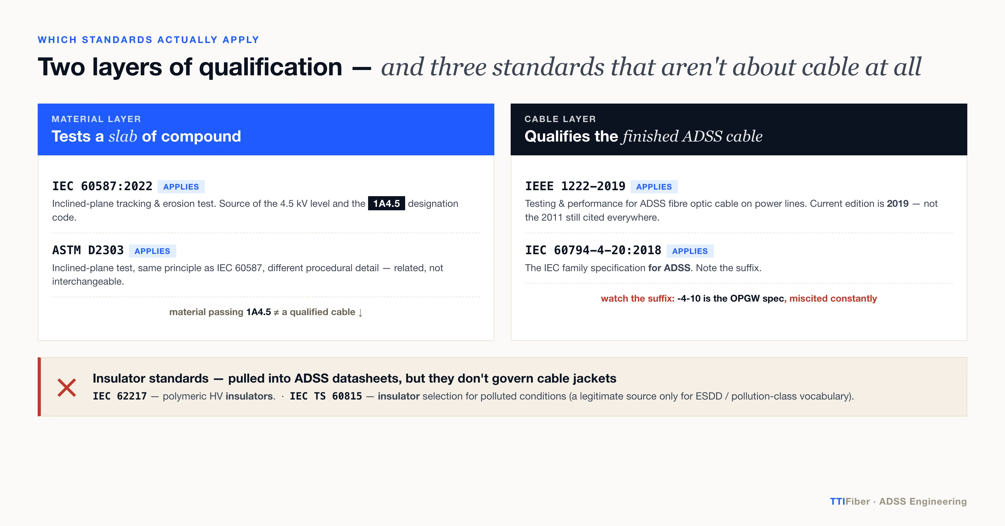
The 4.5 kV figure is real, and it is being quoted at the wrong layer. It comes from the inclined-plane test in IEC 60587, which evaluates a slab of insulating material, not a finished cable. Its proper expression is a designation code, not a bare number: 1A4.5 means Method 1 (constant voltage), Criterion A (leakage current exceeded the limit), at 4.5 kV. A datasheet line reading "anti-tracking: 4.5 kV" without the method and criterion is not a claim you can verify or compare between two suppliers. Ask for the full code and the test report.
"Class A anti-tracking material" has no standard behind it. We looked for one — through IEEE 1222, IEC 60587, IEC 60794-4-20 and ASTM D2303 — and there is nothing that defines those classes for ADSS jackets. It is vendor vocabulary that has propagated by repetition. It might mean 1A4.5. It might mean the supplier's internal grade name. When a datasheet says "Class A," the only correct response is to ask which test, which criterion, and at what voltage.
None of this means the conventions are wrong. The 12/25 kV thresholds are sound and we design to them ourselves. It means that when you are comparing two quotations, the standards references are the part you can actually audit — so it is worth knowing which ones are load-bearing.
For what it's worth on the base polymer: the choice among PE grades is a real one with its own trade-offs in stress-crack resistance and abrasion, covered separately in MDPE vs HDPE for fibre optic cables. Neither grade is track-resistant. Tracking resistance comes from what is compounded into the polyolefin — typically inorganic fillers such as alumina trihydrate that release water endothermically under arc heating and leave a non-carbonising residue.
The standards that apply — and three that don't
Standard | What it actually is | Layer | Applies to ADSS tracking? |
|---|---|---|---|
Testing and Performance for All-Dielectric Self-Supporting (ADSS) Fiber Optic Cable for Use on Electric Utility Power Lines | Finished cable | Yes — the primary cable-level standard. Current edition is 2019 (with Cor 1-2025), not the 2011 edition still cited everywhere. | |
Family specification for ADSS (all-dielectric self-supported) optical cables | Finished cable | Yes — this is the IEC family spec for ADSS. | |
Family specification — Optical ground wires (OPGW) | Finished cable | No. This is the OPGW spec. It is miscited for ADSS constantly. | |
Test methods for evaluating resistance to tracking and erosion of insulating materials under severe ambient conditions | Material | Yes — the inclined-plane test; the source of the 4.5 kV level and the 1A4.5 code. | |
ASTM D2303 | Liquid-contaminant, inclined-plane tracking and erosion of insulating materials | Material | Yes, at material level. Same principle as IEC 60587, different procedural detail — related, not interchangeable. |
Polymeric HV insulators for indoor and outdoor use | Insulator product | No. It is an insulator standard. It invokes inclined-plane testing on housing material, which is why it gets dragged into ADSS discussions, but it does not govern cable jackets. | |
IEC TS 60815 | Selection and dimensioning of HV insulators for polluted conditions | Insulator product | No for selection. It is however where ESDD (equivalent salt deposit density) and the pollution-severity classes come from, and that vocabulary is a legitimate way to describe an ADSS route's environment. |
Two practical tests you can run on any supplier's paperwork:
If an ADSS datasheet cites IEC 60794-4-10, the supplier has cited the OPGW specification. Both standards are real; they are different documents. -4-10 is optical ground wire, -4-20 is ADSS. This one is easy to check and it tells you something about how carefully the rest of the document was assembled.
If a datasheet cites IEC 62217 as evidence of jacket tracking resistance, it is borrowing an insulator standard. Not fraudulent — the underlying material test is the same family — but it is not the right reference, and it means you have not been shown a cable-level qualification.
How the inclined-plane test actually works
Worth understanding, because it is the test whose number you are going to write into your specification.
A slab of the jacket compound is clamped at 45°. Two electrodes sit on the underside — one at the top, one at the bottom. A conductive contaminant solution (ammonium chloride with a wetting agent) is pumped so it flows steadily down the surface between them, through a layer of filter paper that keeps the flow even. Voltage is applied across the electrodes.
The flowing film is doing exactly what dew on a contaminated jacket does at 3 a.m.: carrying leakage current, heating, drying unevenly, forming dry bands, and arcing. The test is a compressed, repeatable version of the field mechanism.
Under Method 1 the voltage is held constant for the duration — at 2.5, 3.5 or 4.5 kV, with 5.0 and 6.0 kV levels defined for higher grades. 4.5 kV is the level the ADSS industry has settled on for a track-resistant jacket, which is why it dominates datasheets. Under Method 2 it is stepped up in increments. The specimen fails on one of two criteria: Criterion A, leakage current exceeds a threshold for a sustained interval; Criterion B, erosion penetrates deeper than a specified depth. Hence 1A4.5 — Method 1, Criterion A, 4.5 kV.
The essential caveat: a compound passing 1A4.5 does not make a cable qualified. Material performance and finished-cable performance are different layers. The jacket in service is extruded to a particular wall thickness over a particular geometry, aged by UV, abraded by hardware, and stressed by a field the flat slab never saw. Cable-level qualification is what IEEE 1222 exists for. Ask for both. A supplier who can produce the material's 60587 code but no cable-level test sequence has qualified half the product.
Independent researchers continue to work on closing exactly this gap between the material test and ADSS service conditions — see, for example, a recent tracking-resistance test proposal for ADSS-type optical cables (abstract open, full text paywalled).
Choosing the jacket: three axes, not one
Most selection tables in this industry have one input — line voltage — and that is why they produce wrong answers at both ends. Use three.
Axis 1 — Space potential at the chosen attachment point. The electrical driver. Below roughly 12 kV, plain polyethylene has three decades of service history. From 12 to 25 kV you need a track-resistant compound. Above 25 kV, no jacket compound alone is a durable answer: reposition the cable, add arc-protection devices at the terminations, or accept that this span may be a case for OPGW rather than ADSS.
Axis 2 — Wetting and contamination severity. The mechanism needs a conductive film to start. A route in a dry inland climate with clean air tolerates a space potential that a coastal, salt-fog, heavy-dew route will not. Borrow the IEC 60815 pollution classes and ESDD vocabulary to state this in a tender — "very heavy pollution, coastal, ESDD class e" is a specification; "harsh environment" is not. Where the site sits near the top of a band on Axis 1, this axis is what breaks the tie.
Axis 3 — Span and mechanical loading. This drives jacket count, and it is worth stating plainly because the two decisions get blurred constantly:
Single vs double jacket is a mechanical decision. PE vs AT is an electrical one.
They are orthogonal. A double PE jacket buys you nothing electrically. A single AT jacket on a short span is perfectly coherent engineering. The two decisions correlate in practice — long spans on tall EHV towers tend to need both more mechanical margin and more electrical margin — which is why product lines bundle them, and why buyers end up believing "double jacket" means "tracking-resistant." It does not.
Nominal line voltage | Typical space potential range at practical attachment points | Jacket material | Notes |
|---|---|---|---|
≤ 35 kV | Low, usually well under 12 kV | PE (MDPE/HDPE) | Track-resistant compound rarely justified. |
66–132 kV | Spans the 12 kV boundary; strongly position-dependent | PE or AT — simulate, don't guess | The band where repositioning most often pays for itself. |
110–220 kV | Commonly 12–25 kV | AT (track-resistant) | Treat AT as the default; verify with simulation. |
≥ 330 kV | Frequently > 25 kV at upper positions | AT plus mitigation | Reposition low on the tower, add arc-protection hardware, or evaluate OPGW. |
Read that table as a starting hypothesis, not an answer. The left column is a proxy; the second column is the actual input. A 132 kV line with the cable slung near the phases can present more electrical stress than a 220 kV line with the cable near the tower body.
Worked example. 220 kV double-circuit, coastal, heavy salt contamination, 380 m ruling span. Axis 1 puts the preferred attachment point at 17 kV — AT territory. Axis 2 (salt fog, persistent dew) removes any temptation to argue the 17 kV down toward a PE compound. Axis 3, driven by the 380 m span and the ice-and-wind case, calls for a double-jacket construction with the aramid content sized to the tension. Result: double-jacket cable, AT outer sheath, 1A4.5 material code specified, cable-level qualification to IEEE 1222-2019. Not because 220 kV says so — because the three axes independently say so.
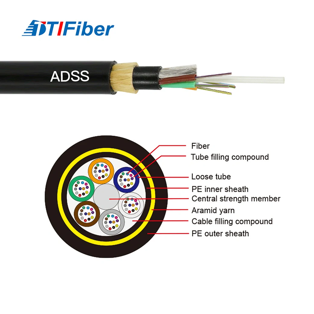
At TTI Fiber we build both branches of this decision, which is the only reason we have opinions about it worth publishing. Our ADSS line runs single-sheath PE for distribution-class routes at 35 kV and below, and double-sheath construction with a track-resistant AT outer jacket for the 110–220 kV band, with aramid content scaled to the span rather than fixed by fibre count. What we would ask any buyer to demand of us — or of anyone else quoting them — is in the next section.
What to put in your specification
The failure mode this section prevents is the one where two quotations look identical, differ by 30% in price, and the cheap one has qualified nothing. Copy this into your technical schedule.
Electrical stress
Jacket material
Finished cable
Environment
Commercial
Frequently asked questions
Does a 33 kV line need an anti-tracking jacket? Usually not. At 33 kV the space potential at practical attachment points is normally well below the 12 kV threshold, and standard PE has a long service record there. Verify rather than assume if the cable must hang unusually close to the conductors.
Is tracking the same thing as corona? No. Corona is ionisation of air adjacent to a high-field surface. Tracking is the formation of a permanent conductive carbon path on a wet, contaminated jacket by repeated dry-band arcing. Corona can accelerate tracking by degrading the surface, but they are distinct mechanisms with distinct remedies.
What is the service life of an ADSS jacket under high space potential? It depends entirely on whether the tracking mechanism initiates. Below threshold with a suitable compound, a well-made ADSS cable is a 30-year asset — the design life we build our double-sheath construction to. Above threshold with a non-track-resistant jacket, field-documented failures have occurred within a few years of energisation. There is no smooth degradation curve between those two outcomes — that is the nature of a self-accelerating mechanism.
Can a tracking-damaged span be repaired? Carbon tracking is not repairable in place. Once a conductive path exists on the jacket, the affected section is replaced. This asymmetry — cheap to specify correctly, expensive to fix — is the entire economic argument for getting Axis 1 right before procurement.
Does OPGW have a tracking problem? No. OPGW is bonded to the shield-wire position and sits at earth potential, so no surface field drives leakage current across it. Its degradation modes are different — corrosion, fatigue, lightning strike damage. That trade-off, along with the live-line installation advantage that makes ADSS attractive in the first place, is the substance of the ADSS vs OPGW decision.
Get the number before you get the quotes
Tracking resistance is not a grade of cable you buy. It is a margin between a material property you can specify and an electrical stress your tower geometry already fixed. The material property is auditable — IEC 60587, Method 1, a designation code, a test report. The electrical stress is computable, cheaply, before anyone quotes anything.
The sequence that goes wrong is: fix the attachment point, tender the cable, let the supplier tell you which jacket you need. The sequence that works is: simulate space potential at two or three candidate positions, discover whether you can attach low enough to make the problem disappear, and only then specify the jacket — with a standards reference that survives being read.
If you want that simulation run against your tower geometry, or a specification reviewed before it goes out, TTI Fiber's ADSS engineering team will do it. Send us the line voltage, phase configuration, tower drawing, and the attachment points you are considering — talk to our ADSS team.
More on cable selection for power utilities, harsh environments and industrial routes in our industrial and harsh-environment fibre collection.