ADSS Sag & Tension Calculation: A Design Guide
ADSS Sag & Tension Calculation: A Design Guide
Here is the thing every ADSS sag-tension calculation comes down to, and the thing almost every guide on the subject gets wrong by omission: ADSS is not limited by how much tension the cable can survive — it's limited by how much strain the glass fiber inside it can survive. A steel conductor is strength-limited; you string it close to its structural rating. An all-dielectric self-supporting cable is fiber-strain-limited, and that single fact pushes its maximum tension down to roughly 40% of its rated strength and changes how you read every number on the sag-tension chart.
This guide walks through the full calculation the way a transmission or OSP design engineer actually has to do it: the catenary relationship, the loading cases, the three tension limits people constantly confuse, the ruling-span method, and a worked example that — unlike most — closes the loop all the way to a fiber-strain check. By the end you'll know what governs your span, what a manufacturer's sag-tension report contains, and where the hand calculation stops and software takes over.
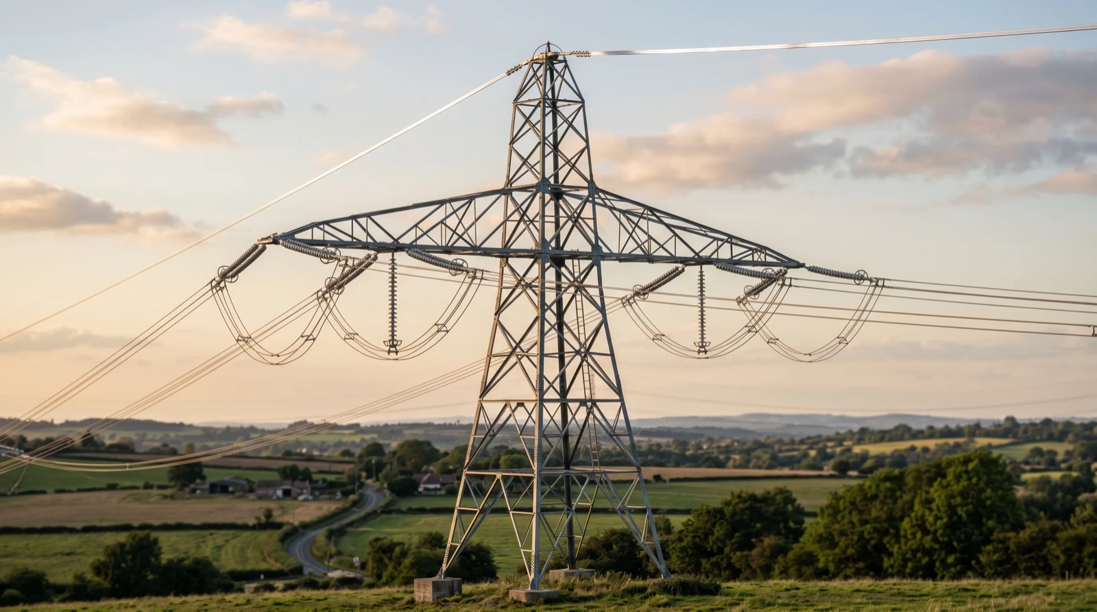
Every span is a catenary. The sag-tension calculation decides how deep that curve is allowed to be — and for ADSS, the fiber inside sets the ceiling.
What "Sag and Tension" Means — and Why ADSS Is Different
A cable hung between two supports forms a catenary — mathematically a hyperbolic cosine, though for the modest sag ratios of most spans a parabola is an accurate and far simpler approximation. The two quantities you solve for are linked by one relationship you should commit to memory:
Sag D ≈ (w · L²) / (8 · H)
where w = cable weight per unit length (including any ice and wind), L = span length, and H = horizontal tension. Read it and the whole topic falls into place: higher tension → less sag; longer span or heavier load → more sag. Tension and sag are two ends of the same lever.
For a bare optical cable on a power line, you might think you simply pull it tight to minimize sag and clear the conductors below. For ADSS you cannot — and the reason is structural. Unlike OPGW, which carries its load on aluminum-clad steel, ADSS carries its entire mechanical load on aramid yarn (Kevlar-type) wrapped around an all-dielectric core, the same metal-free design philosophy as a GYFTY non-metallic cable. The glass fibers themselves sit slack inside gel-filled loose tubes, deliberately decoupled from the cable's tension by a small amount of excess fiber length (EFL). Pull the cable too hard and you use up that slack — at which point the fiber itself begins to stretch, attenuation climbs, and the cable's optical life is compromised long before anything mechanically breaks.
That is why ADSS sag-tension design is, at its core, a problem of keeping the cable's strain below the point where fiber strain begins.
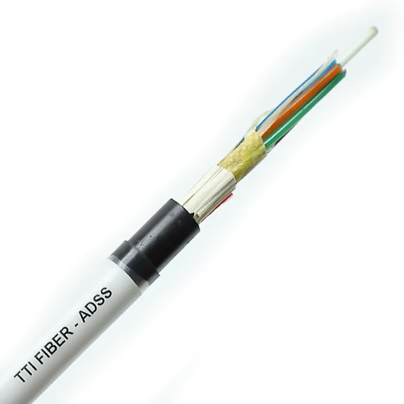
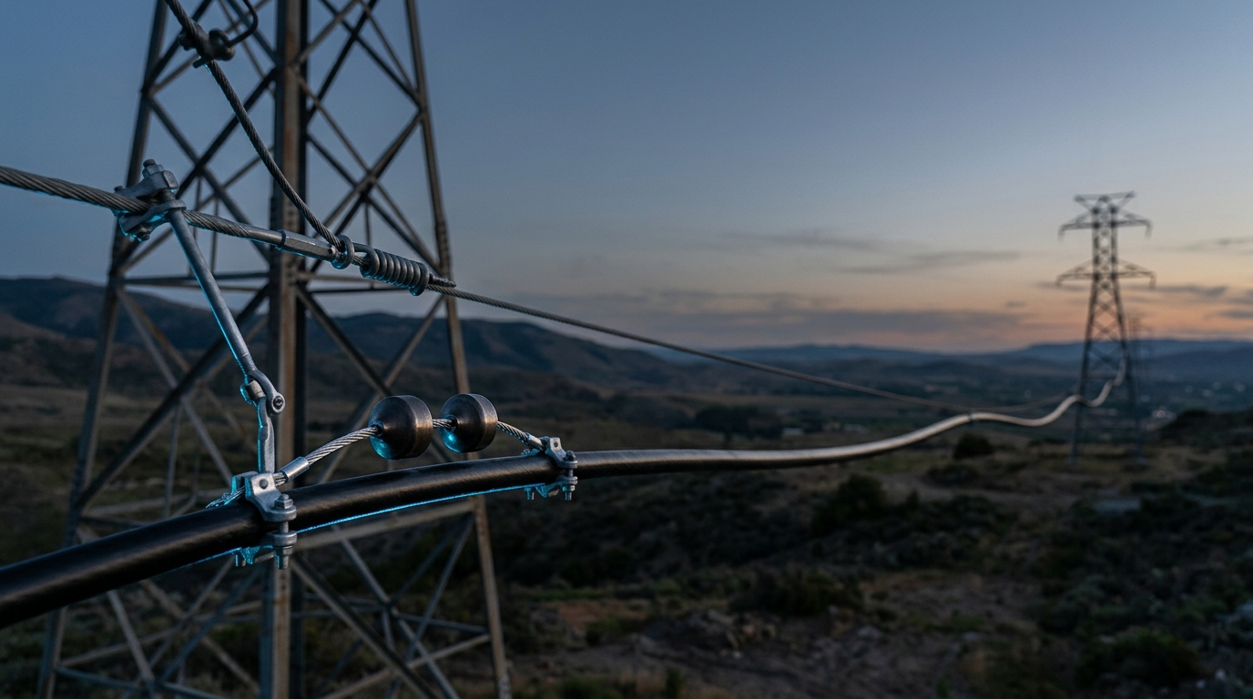
The yellow aramid yarn is the entire load path of an ADSS cable. Its strength sets RTS; its creep behavior sets the difference between initial and final sag.
The Numbers That Govern the Design: RTS, MAT, EDS
Every tension on an ADSS sag-tension chart is expressed as a percentage of one reference value, so start there.
Term | What it is | Typical ADSS value |
|---|---|---|
RTS / RBS (Rated Tensile Strength) | The cable's rated breaking strength — set by the aramid cross-section. The 100% reference. | Spec'd per cable (e.g. 20–60+ kN) |
MAT (Maximum Allowable Tension) | The highest tension permitted under the worst design load (ice + wind + cold). Must not be exceeded. | ~40% of RTS (50–60% for special designs) |
EDS (Every Day Stress) | The resting tension at average temperature with no ice or wind. Drives creep and vibration. | ~16–25% of RTS |
Installation / stringing tension | The tension the cable is actually pulled and sagged-in at. Kept well below MAT. | ~20–25% of RTS |
The headline number — MAT ≈ 40% of RTS — is lower than the 50–60% you'd allow on a metallic conductor, and now you know why: the limit isn't the aramid breaking, it's the fiber straining. The other number engineers should burn in is EDS at roughly 16–25% of RTS. EDS looks like a comfort figure, but it is set by fatigue, not strength: keep everyday tension low enough and wind-induced vibration stays within the cable's endurance limit. We'll come back to that.
Three tension limits, not one. A surprising amount of field trouble comes from conflating them. MAT is a design limit (worst-case load). Installation tension is what you sag the cable in at on a mild day. Pulling tension is the transient limit during stringing (governed by the grip and the sheave bend, often capped to keep fiber strain under ~0.8% momentarily). They are three different numbers and all three must be respected.
Loading Cases: What You're Designing Against
The "worst design load" that sets MAT is a defined weather case, not a guess. In the United States the governing reference is the National Electrical Safety Code (NESC / IEEE C2), which defines three loading districts:
District | Radial ice | Wind | Temperature |
|---|---|---|---|
Heavy | 0.5 in (12.7 mm) | 4 psf (~192 Pa) | 0 °F (−18 °C) |
Medium | 0.25 in (6.35 mm) | 4 psf | +15 °F (−9 °C) |
Light | none | 9 psf (~431 Pa) | +30 °F (−1 °C) |
(Outside the US, IEC 60826 / CIGRE supply an equivalent reliability-based loading framework.) Ice and wind don't simply add — they combine as a vector. The total load per unit length is:
W_total = √[ (W_cable + W_ice)² + (W_wind)² ]
Ice loads the cable vertically and, just as importantly, fattens its diameter, which increases the area the wind pushes on. That coupling is why a "heavy" district can multiply the effective load on a thin cable several times over — and why the cold, iced case, not the hot summer day, usually sets your maximum tension.
Creep and the Initial-vs-Final Curve
A metallic conductor and an ADSS cable both creep — elongate slowly and permanently under sustained load — but aramid creeps differently, and a good calculation models it explicitly. This is why a proper sag-tension report shows two curves at every temperature: initial (freshly strung) and final (after years of creep and load settling). The final curve sags more. (Temperature swings move sag directly, and they also affect the fiber's optical performance — both reasons the chart spans the full design temperature range.)
Practically, ADSS modeling requires not one modulus of elasticity but a set — an initial modulus, a final-after-creep modulus, and often a 10-year value — plus the aramid's coefficient of thermal expansion. As the PLS-CADD technical note on modeling ADSS lays out, these are exactly the inputs the software needs to predict cable behavior over its life. For long spans, manufacturers also build in a creep allowance (extra aramid) so that decades of settling don't pull the fiber into strain. If a "sag-tension calculation" you're handed shows only a single curve, it hasn't accounted for creep — treat it with suspicion.
The Real Ceiling: Fiber Strain and Zero Fiber Strain Margin
This is the section every competitor skips, and it's the one that matters most.
Inside an ADSS cable the fiber is longer than the tube that houses it — that surplus is the excess fiber length (EFL). As the cable tensions and stretches, it first consumes that slack while the fiber sees essentially zero strain. The tension at which the slack runs out — where the fiber is about to start stretching — is the Zero Fiber Strain Margin (ZFSM), also reflected in the spec value some software calls MRCL (Maximum Rated Cable Load). Push past it and you reach the knee point: fiber strain rises, and with it, attenuation — one of the main causes of loss in a fiber link.
The whole design is built around staying on the safe side of that knee:
- At EDS, the fiber should see essentially zero strain for the life of the line.
- At MAT (the worst-case storm), fiber strain should stay within a tight allowance — commonly cited around ≤ 0.05% for stranded designs — well below the level that would degrade the optics.
- The short-term ultimate condition (rare overload) tolerates more, on the order of a few tenths of a percent.
The governing standards put numbers and tests behind this. IEEE 1222 defines the mechanical, environmental, and optical performance tests an ADSS cable must pass for utility lines, and IEC 60794-4 — the sectional spec for aerial cables along power lines — defines the permissible fiber strain at EDS and MAT for the single-mode fiber (ITU-T G.652) inside. The reason MAT lands near 40% of RTS rather than 60% is precisely to keep the cable below ZFSM under the storm load. Strain, not strength, is the ceiling.
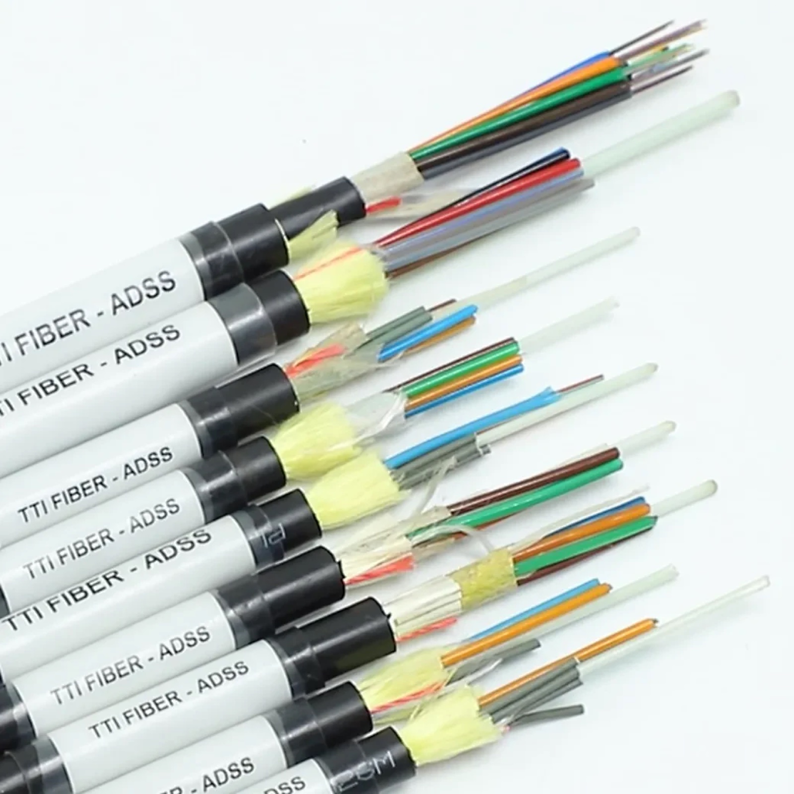
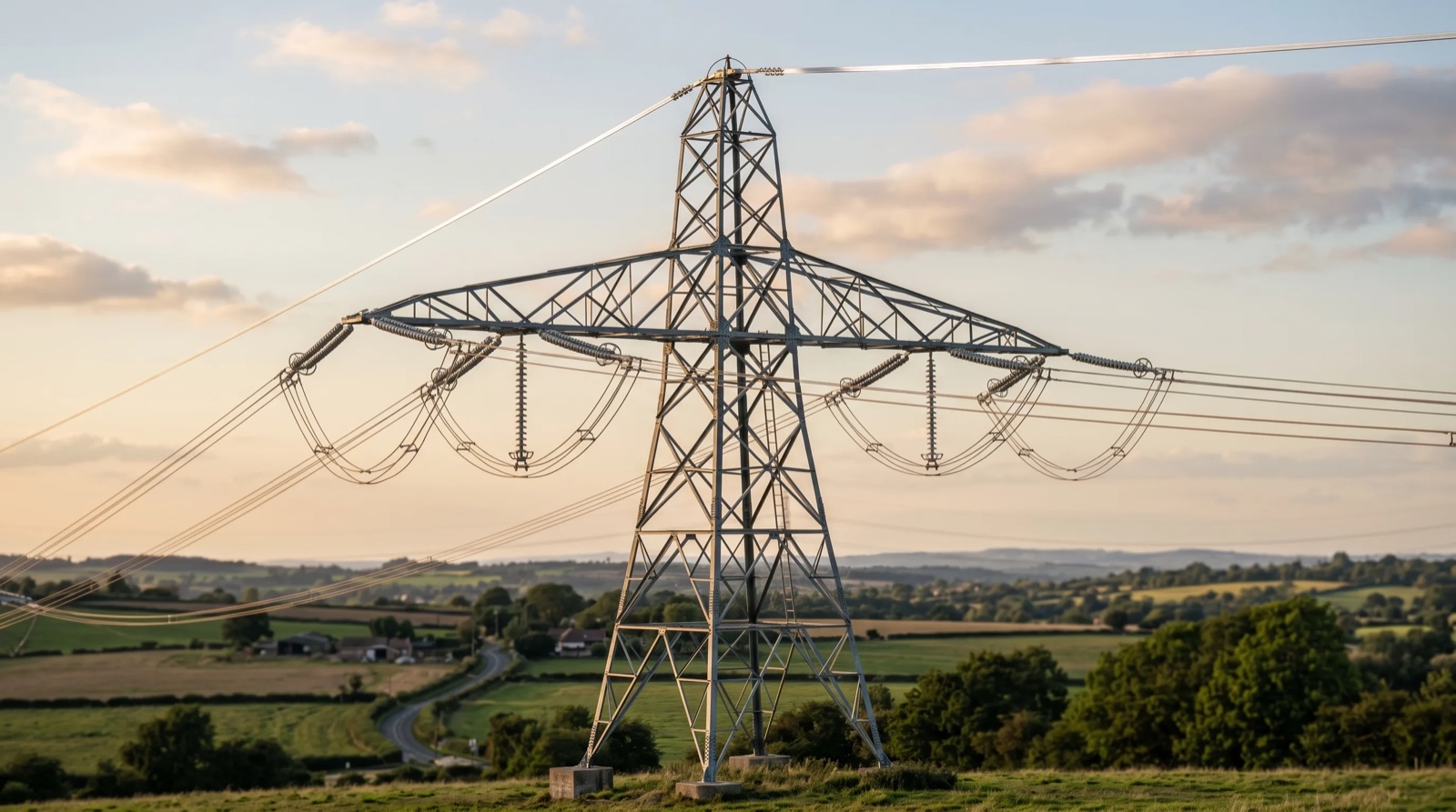
Fiber count and aramid content are matched to the span. The excess fiber length built into each design is what creates the strain margin between EDS, MAT, and the knee point.
Ruling Span: One Tension for a Whole Section
You rarely design span-by-span. Between two dead-end (tension) structures, a line runs through several suspension structures, and the cable tension equalizes across all of them. So you design the section around a single ruling span (equivalent span):
Ruling Span = √( ΣL³ / ΣL )
— the cube-weighted average of the individual span lengths. The sag-tension chart is computed for that ruling span, and the field crew strings the entire section to it. The approximation holds well when the spans are reasonably similar; when one span is dramatically longer than its neighbors (roughly a 3:1 ratio or more), or the terrain is steeply inclined, the simple ruling span breaks down and you move to a full finite-element model.
A Worked Example (Carried Through to Fiber Strain)
Take a 300 m distribution span, an ADSS cable of ~16 mm diameter, ~180 kg/km weight (≈ 1.8 N/m bare), and RTS = 30 kN. So MAT ≈ 0.40 × 30 = 12 kN, and EDS ≈ 0.20 × 30 = 6 kN.
1 — Everyday sag (EDS, no ice/wind). Using D ≈ wL²/(8H):
D = (1.8 × 300²) / (8 × 6000) = 162,000 / 48,000 ≈ 3.4 m (sag ratio ~1.1%)
2 — Storm load (NESC Medium: 0.25 in ice + 4 psf wind). Iced diameter ≈ 16 + 2(6.35) = 28.7 mm.
W_ice ≈ 3.9 N/m (annular ice ring, ρ ≈ 900 kg/m³)W_wind ≈ 192 Pa × 0.0287 m ≈ 5.5 N/mW_total = √[(1.8 + 3.9)² + 5.5²] = √(32.5 + 30.3) ≈ 7.9 N/m (≈ 4.4× the bare weight)
3 — Tension check. Feed that load and the cold temperature into the change-of-state (sag-tension) solver. Suppose it returns a maximum tension of ~10 kN at the iced/cold case. That is below MAT (12 kN) ✓ — the structural check passes.
4 — The check the others skip: fiber strain. Now confirm that at ~10 kN the cable's elongation is still within its excess fiber length, so fiber strain stays ≈ 0 (and ≤ the ~0.05% allowance at the very worst case). If it isn't, you don't tighten a bolt — you specify a higher-RTS cable (more aramid) or shorten the span. This is the step that makes it an ADSS calculation rather than a generic conductor calculation.
5 — Output: the stringing sag. Finally, the solver gives the installer the sag to dial in at the actual installation temperature — e.g. "string to 2.8 m at 20 °C" — across the full temperature range.
The load-vector math above is exact and you can do it by hand. Step 3's tension and step 4's strain come from a change-of-state solution that iterates initial/final modulus, creep, and temperature — that's what software (SAG10, PLS-CADD, ACES CATS) and a manufacturer's sag-tension report are for. Treat any single hand-computed tension as a sanity check, not a construction value.
Why ADSS Is Strung Looser Than OPGW: Aeolian Vibration
Return to EDS for a moment, because it explains a question installers often ask: why string ADSS slacker than the OPGW on the same towers? The answer is aeolian vibration — the high-frequency, low-amplitude flutter a steady wind induces in any taut cable. Its severity scales with the tension-to-weight ratio (H/w): the tighter and lighter the cable, the more readily it resonates and the faster it fatigues at the clamps.
ADSS is light, so at a given tension its H/w — and its vibration risk — is high. Utilities therefore cap EDS (that 16–25% RTS band) specifically to keep vibration within the cable's endurance limit, and add Stockbridge dampers and cushioned suspension hardware on longer or higher-tension spans. (Galloping — the low-frequency, high-amplitude motion of an iced cable — is a separate dynamic case checked for clearance.) OPGW, being heavier and strength-limited, tolerates a higher tension; ADSS, being light and strain-limited, does not. Same towers, different rules.
How to Read a Manufacturer's Sag-Tension Chart
The deliverable of all this is a sag-tension report the manufacturer produces for your specific cable, span, and loading. It generally comes as one of three table types:
- Constant installation sag — sag held constant, tension varying with temperature.
- Constant installation tension — tension held constant, sag varying with temperature.
- Constant (final) load — the after-creep condition used for clearance checks.
A usable chart lists, at 5 °C increments across the design temperature range, both the initial and final sag and tension, with the no-ice baseline (often 0 °C) called out, and the maximum-load case flagged against MAT. To use it in the field, the crew finds the current ambient temperature, reads the target stringing sag, and sags the cable in to it — typically waiting roughly a day after pulling for the cable to settle before taking the final sag.
Frequently Asked Questions
How do you calculate sag and tension for ADSS? Start from D ≈ wL²/(8H), define the loading cases (ice/wind/temperature), then solve the change-of-state equation for tension across the temperature range — checking the result against both MAT and the fiber-strain limit. The load math is by hand; the tension/strain solution is by software or a manufacturer report.
What is MAT for ADSS? Maximum Allowable Tension — the highest tension permitted under the worst design load, typically about 40% of RTS (higher for special long-span designs). It's set so the fiber stays below its strain limit during a storm.
What tension should ADSS be installed at? Installation (stringing) tension is usually around 20–25% of RTS, near EDS — low enough to protect the fiber and limit aeolian vibration. The exact sag to string to comes from the sag-tension chart at the day's temperature.
Does ADSS sag more than OPGW? Yes. ADSS is strung at lower tension (it's strain-limited and vibration-sensitive), so it sags more than the heavier, stiffer OPGW on the same span. Clearance design must account for it.
What is the maximum span for ADSS? Roughly 50–200 m for distribution, commonly up to ~700 m on transmission, and beyond 1,000–1,500 m for special long-span designs with extra aramid — always bounded by the fiber-strain limit under the site's loading.
How much fiber strain is too much? The cable is designed so the fiber sees ~0 strain at EDS and stays within a small allowance (commonly cited ≤ ~0.05% for stranded designs) even at MAT. Beyond the knee point, attenuation rises and long-term reliability drops.
The Bottom Line
An ADSS sag-tension calculation is not a conductor calculation with a different cable pasted in. The catenary math is the same, but the governing limit moves: from "how much tension can the cable survive" to "how much can the cable stretch before the fiber inside it strains." Get the loading cases right, respect the three different tension limits, model creep with initial and final curves, and — above all — carry every design all the way through to a fiber-strain check against ZFSM. Do that and the cable will hold sag, clearance, and optical performance for its full service life. Skip the strain check, and you can pass every structural number and still slowly degrade the fiber you were paid to protect.
--- TTI Fiber manufactures ADSS all-dielectric self-supporting cable with aramid content and excess fiber length engineered to your span and loading. Request a project-specific sag-tension report — initial/final sag and tension across your temperature range, checked against MAT and fiber strain — for your route.