Submarine Cable Basics: From Seabed to Landing
Submarine Cable Basics: From Seabed to Landing
There are more than 600 submarine cables in service or planned today, carrying over 1.5 million kilometers of glass fiber across ocean floors worldwide — and nearly all of the world's international internet traffic runs through them, according to TeleGeography's submarine cable data, the industry's most-cited tracker of these figures. Satellites, by comparison, carry well under half a percent of U.S. international capacity. Yet ask most explainers what a submarine cable actually is, and they'll walk you through the fiber, the repeaters, the cable ship — then stop the moment the cable reaches the beach.
That's the gap this guide fills. We'll cover the real basics: what's inside a submarine cable, how it transmits data, how it's laid, and what actually breaks it (it's not sharks). But we'll also go one step further than most sources bother to: what physically happens once the cable comes ashore, and what kind of cable and hardware picks up the signal from there — because that handoff is where a submarine system stops being a marine engineering project and becomes a piece of terrestrial network infrastructure.
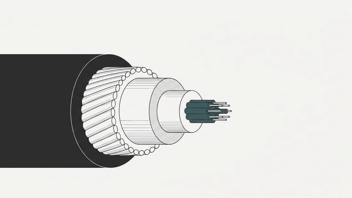
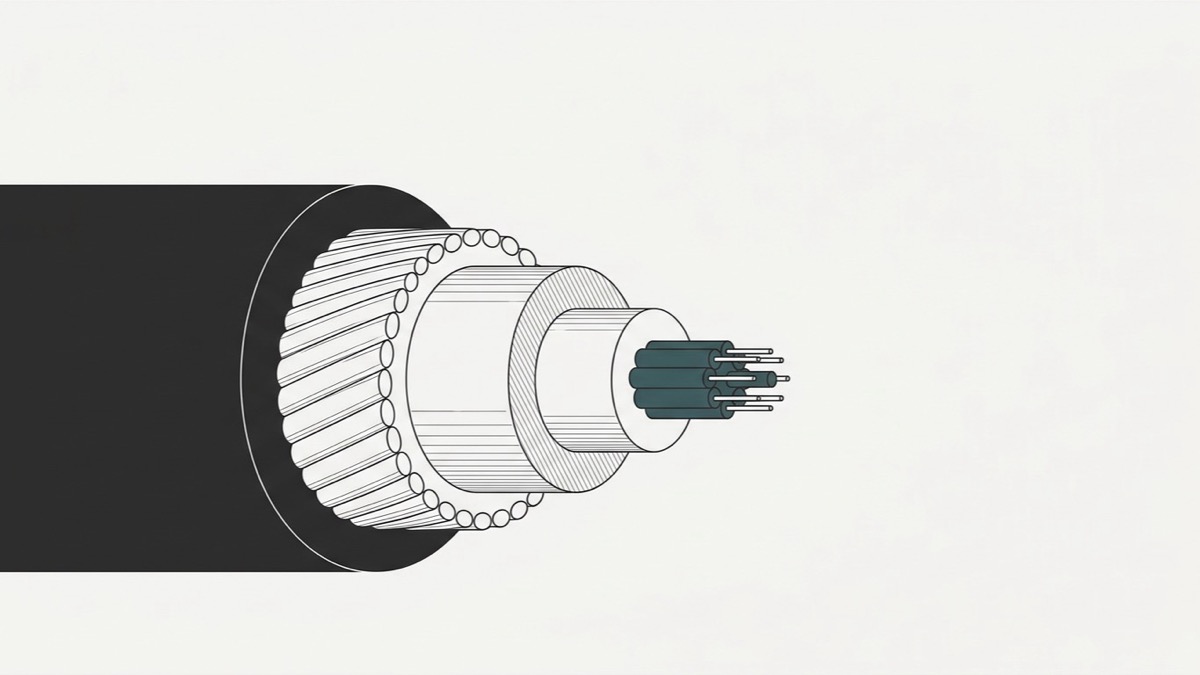
Anatomy of a submarine cable, end-on: outer jacket, steel wire armor, copper power-conductor tube, and the fiber core at the center.
Anatomy of a Submarine Cable: What's Inside That "Garden Hose"
A submarine cable's job description is deceptively simple: get laser light from one shore to another without letting the ocean interfere. Structurally, it's built like a set of concentric defenses around a fragile core.
At the center are the optical fibers — hair-thin strands of glass that carry the signal as pulses of laser light, cushioned in petroleum jelly or a similar gel that keeps water out even if the outer layers are breached. Around that sits a copper or aluminum tube, which does something a terrestrial fiber cable's core never needs to do: carry electrical power. Submarine systems run 3,000 to 4,000 volts of DC current down the cable's length to feed the repeaters spaced along the route — there's no wall outlet on the ocean floor.
Outside the power conductor, a polycarbonate layer and an aluminum water barrier add another line of defense against pressure and moisture, and then — for the sections that actually need it — stranded steel wires wrap the whole assembly for mechanical protection, finished with an outer polyethylene jacket. Wikipedia's cross-section of a shore-end cable lists this exact layer stack: polyethylene, Mylar tape, steel wire armor, aluminum water barrier, polycarbonate, copper or aluminum tube, petroleum jelly, and finally the fiber core.
Notice the qualifier: shore-end. That steel wire armor isn't uniform along the cable's length, and this is the detail most explainers skip. In deep water, where the cable rests below fishing nets, anchors, and most human activity, it often needs no armor at all — a lightweight, unarmored design keeps cost and weight down over thousands of kilometers, and modern deep-sea cable typically runs about 25 mm in diameter (closer to a garden hose than a pipe) at roughly 1.4 tonnes per kilometer. Closer to shore, where trawlers, anchors, and tidal movement are real threats, cable designers add one or two layers of galvanized steel wire armor, sometimes doubling the diameter and weight. It's the same logic any armored outdoor cable manufacturer applies on land: protection scales with the specific threat at that point in the route, not a single one-size-fits-all spec.
Where a system serves more than two landing points, a submarine branching unit splits the optical and power paths underwater, routing traffic to each branch without surfacing — the subsea equivalent of a junction box, engineered to survive decades at ocean-floor pressure.
How a Submarine Cable Actually Carries Data
The transmission mechanism is straightforward in concept, even if the engineering behind it isn't. At each end, laser transmitters encode data as pulses of light and fire them down the glass fiber at wavelengths invisible to the human eye. Glass is an excellent conductor of light, but not a perfect one — over distance, the signal weakens and needs boosting.
That's the job of the repeaters lined up along the cable, spaced roughly every 60 to 100 kilometers depending on the system's design and vintage. Modern repeaters use erbium-doped fiber amplifiers (EDFAs) — a length of fiber doped with erbium ions that, when hit with a separate pump laser, amplifies the passing signal directly in the optical domain rather than converting it to electricity and back. Every one of those repeaters draws its power from the same copper conductor described above, which is exactly why the cable's electrical design and optical design have to be engineered together rather than as separate problems.
To multiply how much data a single fiber pair can carry, systems use wavelength-division multiplexing (WDM) — sending dozens of separate wavelengths of light down the same physical fiber simultaneously, each acting as an independent channel. It's how a cable no thicker than a garden hose can carry hundreds of terabits per second. The MAREA cable, a transatlantic system backed by Microsoft and Meta, is rated for roughly 224 terabits per second of potential capacity — enough for tens of millions of HD video streams at once.
That capacity has to go somewhere once it reaches shore: it's decoded back into a terrestrial-optical signal at the cable landing station, by equipment called SLTE (submarine line terminal equipment) — the point where the undersea system formally ends and the terrestrial network begins.
From Ship to Seabed: How Submarine Cables Are Installed
Before a single meter of cable goes in the water, marine surveyors spend months mapping the proposed route, looking for seafloor that's stable, free of fault lines, and clear of existing infrastructure. Landing points themselves are chosen just as carefully: per Wikipedia's entry on cable landing points, ideal sites have light marine traffic (to avoid anchor and trawler damage), a gently sloping sandy or silty seafloor (so the cable can be buried), and minimal current (so buried cable stays buried). Suitable sites are rare enough that several cable systems often share the same landing point.
Actual installation is done by purpose-built cable ships, which pay out cable from massive tanks below deck at a controlled rate matched to the ship's speed and the seafloor's contours. A small number of specialized manufacturer-installers build and lay most of the world's systems — SubCom (which supplied MAREA) and Alcatel Submarine Networks (part of Nokia) are the two names behind the majority of active and planned cables. In deep water — generally beyond about 1,500-2,000 meters — the cable is simply laid on the ocean floor; at that depth it's below virtually all fishing and anchoring activity, so burial adds cost without adding meaningful protection. In shallower water near shore, a submersible plow or a remotely operated vehicle with a water jet cuts a narrow trench and buries the cable roughly half a meter to a meter and a half deep, right behind the ship as it moves. A single transoceanic system can take a fleet of ships several months to lay, test, and commission before it ever carries live traffic.
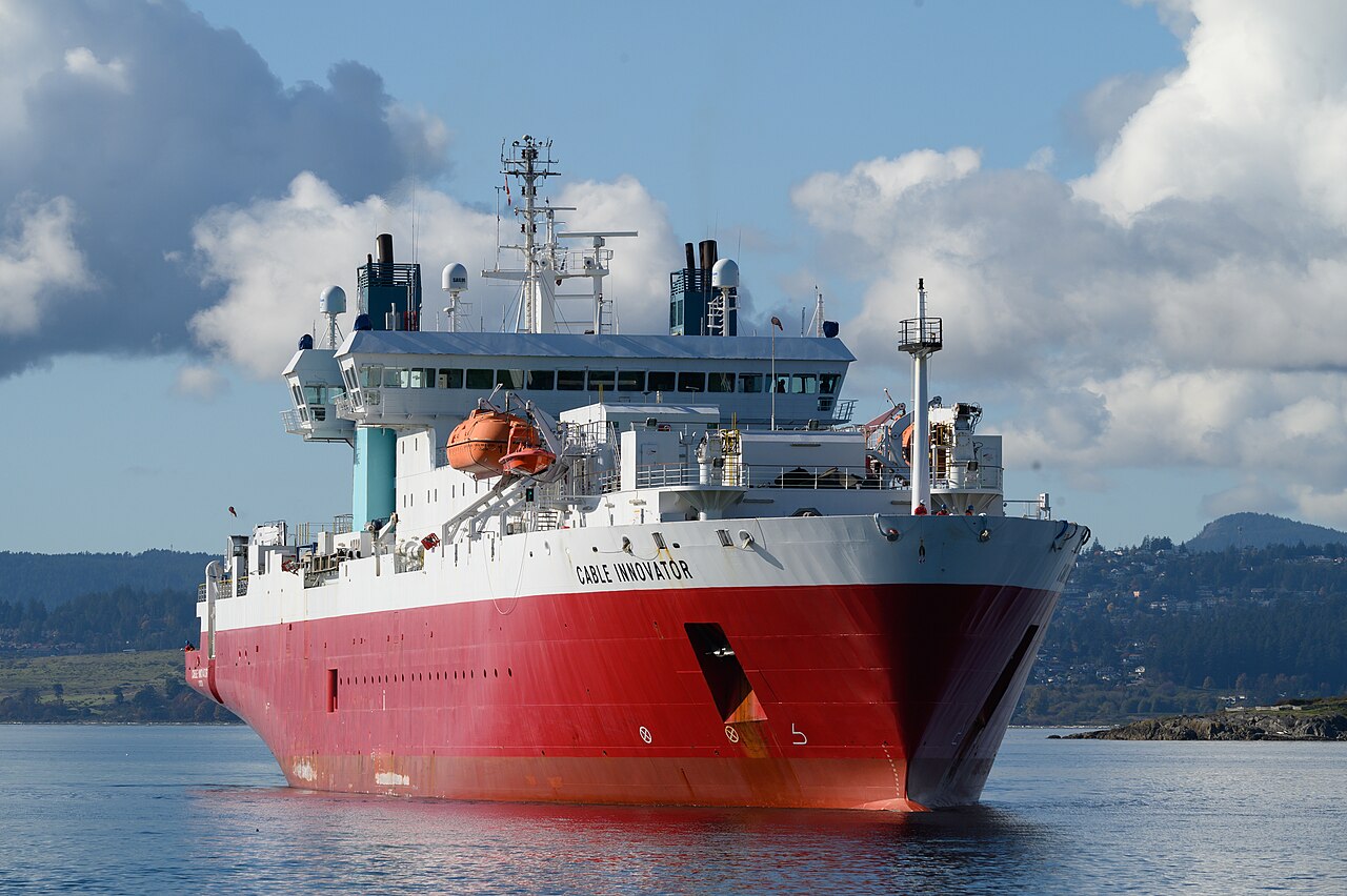
Photo by Gordon Leggett via Wikimedia Commons, CC BY 4.0
This is also where the earlier point about armor pays off in practice: the sections getting buried and exposed to the most mechanical stress are exactly the sections built with heavier steel-wire armor. The lightweight, unarmored deep-sea cable never has to survive a plow blade or a dragged anchor; the shore-end cable does.
What Actually Breaks a Submarine Cable (Hint: It's Not Sharks)
According to the International Cable Protection Committee, roughly 200 submarine cable faults happen every year worldwide. Popular imagination blames sharks. The data doesn't: according to ICPC figures cited by TeleGeography, fish bites — the category that includes sharks — accounted for zero recorded cable faults between 2007 and 2014. Roughly two-thirds of all faults are caused by fishing vessels and ship anchors dragging across cable routes; the rest come from natural events like earthquakes and undersea landslides, with equipment failure and deliberate sabotage trailing well behind.
The shark myth isn't entirely baseless, though — it has a real, well-documented origin. In 1985, AT&T laid a trial fiber-optic cable off the Canary Islands without the electrical shielding used on older coaxial cables. Sharks, apparently drawn to the electrical field or the vibration of the unsecured cable, attacked it repeatedly, triggering feeding frenzies severe enough to cause outages. TAT-8, the first transatlantic fiber cable, was already years into development when that happened — but it went into service in 1988 with dedicated shark shielding added as a direct result of the incident, and cables built since have inherited some version of that lesson, even though the actual bite rate turned out to be far lower than the Canary Islands incident suggested.
When a fault does happen, a specialized cable repair ship locates the break (often within a few hundred meters, using OTDR — optical time-domain reflectometer — readings from shore-side monitoring equipment to pinpoint the distance to the fault), grapples the cable up from the seafloor, splices in a new section, and re-lays it — a process that can take anywhere from a few days to several weeks depending on weather, depth, and ship availability. It's exactly why network operators design for redundancy rather than resilience of any single cable: spread capacity across multiple routes, and one fault becomes a maintenance event instead of an outage.
Submarine Cable vs. Terrestrial Fiber Cable: What Actually Changes
Once you understand what a submarine cable actually is, a natural question follows: how different is it, really, from the outdoor fiber cable used on land? The honest answer is: more than the shared "fiber optic cable" label suggests.
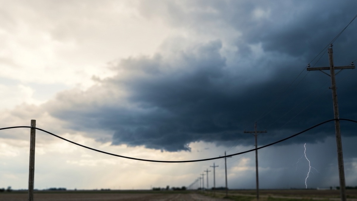
The biggest structural difference is the power conductor. Submarine cables carry their own copper or aluminum tube to feed repeaters thousands of kilometers from the nearest power source — there's no equivalent on land, where network equipment simply plugs into the grid. Terrestrial outdoor cable, by contrast, is often built all-dielectric — no metal at all — specifically to eliminate the risks that come with carrying current, like induced voltage near power lines or lightning attraction. ADSS (all-dielectric self-supporting) cable, used for aerial spans along power corridors, is the clearest example: it's engineered to have zero metallic content for exactly the opposite reason a submarine cable is engineered to have a metal core.
Armor logic differs too, even though both cable types use it. Submarine cable armor is graded by ocean depth and proximity to fishing and shipping activity; terrestrial armored cable — the kind used for direct burial, duct routes, or road crossings — is graded by soil conditions, rodent activity, vehicle loading, and installation method. The materials (steel wire, steel tape) overlap, but the design inputs don't.
Design life is roughly comparable — submarine systems are typically engineered for about 25 years, in the same range as well-specified terrestrial OSP cable — but the failure modes and repair economics are worlds apart. A terrestrial fault gets a splice crew and a bucket truck or an excavator; a submarine fault gets a specialized ship that may need weeks to reach the site. That gap is exactly why the transition point between the two systems — where a submarine cable's responsibility ends and terrestrial cable's begins — deserves more attention than it usually gets. That's the last piece of this guide.
What Happens When a Submarine Cable Reaches Land
This is the part almost every submarine cable explainer skips, and it's the part that matters most if you actually work in terrestrial network infrastructure.
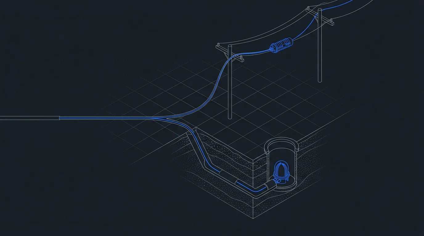
The submarine cable's journey doesn't end at the water's edge. It comes ashore through a beach manhole (BMH) — a small, unglamorous concrete vault, often just above the high-tide line, where the wet-plant cable terminates and a short, unrepeatered land cable (the "dry plant") takes over for the final stretch to the cable landing station (CLS). That stretch can be a few hundred meters or several kilometers, depending on the site — it just needs to get the signal to a building that can house sensitive electronics safely away from the water.
Inside the CLS sits the SLTE (submarine line terminal equipment) that decodes the optical signal, and the PFE (power feeding equipment) that supplies the 3,000-4,000 volt DC current running down the cable to power every repeater along the route.
Here's the detail that matters most for anyone planning what comes next: the CLS is not necessarily the end of the line. Per Wikipedia's entry on cable landing points, the CLS may double as a cable termination station — where the submarine system formally hands off to the land-based backhaul network — or that termination point can sit miles inland, connected to the CLS by conventional terrestrial cable, because landing sites are chosen for coastal geography, not population density or network topology.
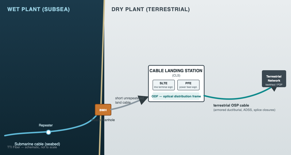
The handoff nobody else diagrams: wet plant → beach manhole → cable landing station (SLTE + PFE) → ODF → terrestrial OSP cable into the network.
That inland stretch is squarely terrestrial OSP territory, and it's built with the same categories of cable and hardware used on any long-haul or metro fiber route:
- Armored duct or direct-burial cable for the underground run from the BMH or CLS toward the inland network — the same steel-tape or steel-wire armored construction discussed earlier, sized for soil conditions and burial method rather than ocean depth.
- Splice closures, rated for outdoor and direct-burial exposure, at the BMH-to-dry-plant transition and again wherever the terrestrial route needs a joint — sealing out moisture the same way the cable's own layers do underwater, just engineered for a different environment.
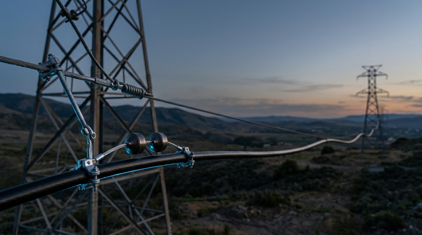
- ADSS aerial cable, if the route from the CLS to the inland network runs along existing utility poles rather than underground — common when a landing station sits somewhere the local grid already reaches by pole line.
- An ODF (optical distribution frame) inside the CLS itself, where the SLTE's terrestrial-side output gets patched, tested, and handed off cleanly to whatever network — a carrier's backbone, a hyperscaler's private route, an internet exchange — picks it up from there.
None of this is submarine engineering anymore. It's the same outside-plant fiber infrastructure used on any terrestrial route, which is exactly the point: understanding submarine cable basics means understanding where the marine engineering problem ends and the terrestrial engineering problem begins, because that boundary is where most of the world's actual network build-out work happens.
Quick Answers
How deep are submarine cables laid? Anywhere from a few meters near shore to more than 8,000 meters in the deepest ocean trenches. Cables are only buried in shallower water (typically under 1,500-2,000 meters); beyond that depth, they're laid directly on the seafloor.
Who owns submarine cables today? Historically, consortiums of telecom carriers. Increasingly, hyperscalers — Google, Meta, Microsoft, and Amazon are now major investors and, in some cases, sole owners of new systems, driven by their own bandwidth demand between data centers.
How much data can a submarine cable carry? It depends on the system's age and fiber-pair count, but modern cables are commonly rated in the hundreds of terabits per second — MAREA, for example, carries up to 224 Tbps of potential capacity.
Are submarine communications cables the same as submarine power cables? No. Submarine communications cables carry data on optical fiber and use a small DC current only to power repeaters. Submarine power cables carry high-voltage AC or DC power itself, at a completely different scale — some run in the hundreds of kilovolts.
Where TTI Fiber Fits
Submarine cable is genuinely fascinating marine engineering — but for anyone working in network infrastructure, the more useful takeaway is the boundary this guide keeps returning to: the point where a subsea system stops being a marine problem and becomes a terrestrial one. TTI Fiber doesn't build the wet-plant cable that crosses the ocean floor — that's specialized subsea engineering outside our scope. What we do build is everything on the other side of that beach manhole: armored duct and direct-burial cable, splice closures rated for outdoor and buried environments, and ADSS all-dielectric cable for aerial approach spans — the outside-plant infrastructure that actually carries a submarine system's traffic the rest of the way inland. If you're specifying cable for a landing-station approach route or any other OSP build, talk to our engineers about what the terrestrial side of that project actually needs.